




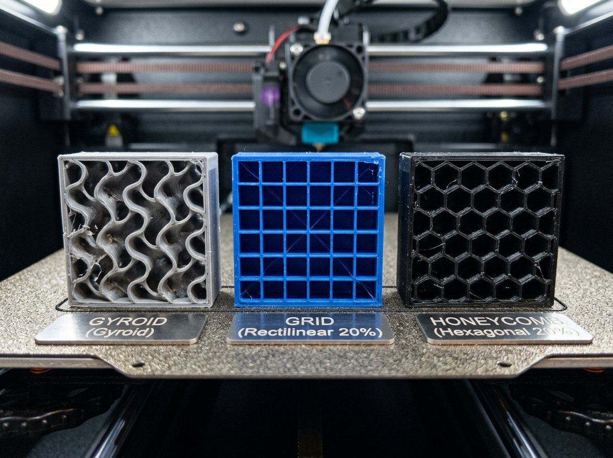
Internal infill pattern selection dictates the mechanical behavior, print duration, material consumption, and operational stability of modern FDM prints. While default slicer profiles frequently recommend Grid or Rectilinear infill, high-speed CoreXY machines often experience severe nozzle dragging and frame resonance when printing grid geometries. This technical guide evaluates the engineering trade-offs between Gyroid, Grid, Honeycomb, and 3D Cubic infill patterns to help makers optimize structural performance and print reliability.
Table of Contents
- Why Gyroid Infill is Superior for Isotropic Part Strength
- Mathematical Physics of TPMS Structures in Slicing
- Grid vs. Cubic vs. Honeycomb: Speed vs. Mechanical Stress
- Modern Infill Alternatives: Cross Hatch and Triangles
- Optimal Infill Percentages for Functional FDM Parts
- Preventing Nozzle Collisions and High-Speed Vibrations
- Thermal Expansion and Volumetric Pressure Spikes
- Slicer Benchmarks and Material Usage Comparison
- Frequently Asked Questions
- References & External Sources
- About the Author: Dinu Suciu
Why Gyroid Infill is Superior for Isotropic Part Strength
Gyroid infill delivers balanced, three-dimensional strength across the X, Y, and Z axes without creating intersecting line crossings on any individual print layer. Its continuous sinusoidal wave geometry distributes mechanical loads uniformly in all directions, making it ideal for functional components subjected to multi-axis torsional and shear stress.
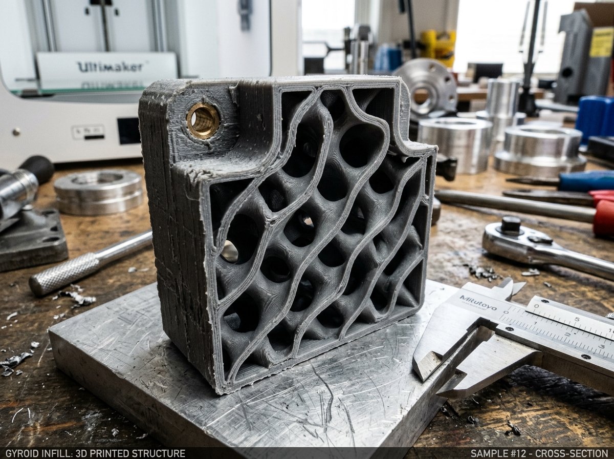
Unlike 2D infill patterns such as Grid or Rectilinear, which build vertical walls that excel only under unidirectional compression, the Gyroid pattern is mathematically derived from a triply periodic minimal surface (TPMS). Because the continuous wave shifts slightly in X and Y on every Z step, forces applied to the external shell spread smoothly through the internal cavity rather than concentrating along flat planar boundaries.
Maker's Workshop Note
In my workshop testing on a Bambu Lab P1S and a Creality K1 using Polymaker PolyLite PLA at 220°C with 15% infill, functional mounting brackets printed with Gyroid withstand multi-directional flexing significantly better than identical brackets printed with Grid infill. Under shear forces, Grid-infill parts tend to delaminate cleanly along the straight extrusion grid lines, whereas Gyroid-infill parts deform predictably without catastrophic internal shear splitting.
Key structural advantages of Gyroid infill include:
- Isotropic Mechanical Resistance: Structural load capabilities remain consistent regardless of whether force is applied parallel or perpendicular to the build plate.
- No-Crossing Geometry: The nozzle moves in continuous sweeping curves without ever crossing previously extruded paths on the same layer.
- Fluid and Resin Drainage: Because the internal cells form an open interconnected network, liquid resins, trapped air, or moisture can drain freely during post-processing or washing cycles.
- Vibration Suppression: Smooth directional changes prevent violent motor direction reversals during rapid toolhead accelerations above 300 mm/s.
Mathematical Physics of TPMS Structures in Slicing
Triply Periodic Minimal Surfaces (TPMS) are mathematically defined non-self-intersecting continuous surfaces in three-dimensional space that exhibit zero mean curvature at every point. In modern 3D printing slicers like Orca Slicer, PrusaSlicer, and Bambu Studio, the Gyroid surface equation sin(x)cos(y) + sin(y)cos(z) + sin(z)cos(x) = 0 is sliced into two-dimensional layer slices that produce continuously phase-shifted sine waves.
As the printer advances vertically along the Z-axis, each successive layer rotates and shifts the phase of the sinusoidal wave. This produces a hollow, wave-like labyrinth where no single vertical plane forms a weak shear joint. Because there are no flat vertical walls, internal shear stress cannot propagate along straight line fractures. Furthermore, the absence of sharp internal 90-degree corners reduces localized stress concentrations, preventing premature crack propagation under fatigue loading.
When printing flexible filaments like TPU or dampening components, the TPMS wave geometry acts like a microscopic mechanical spring matrix. Under compression, the sinusoidal walls flex elastically and spring back into shape, whereas rigid straight-walled infills like Grid buckle permanently or crease under compressive impact.
Grid vs. Cubic vs. Honeycomb: Speed vs. Mechanical Stress
Grid infill prints up to 15% faster on straight linear passes than wavy or complex geometric infills, but it forces the nozzle to cross existing extrusion lines at every intersection on the same layer. This repeated cross-over creates microscopic high spots that cause nozzle friction, audible clicking, and potential print detachment on high-speed FDM printers.
Understanding the mechanical trade-offs between traditional and modern infill geometries helps in selecting the appropriate pattern for specific part applications:
1. Grid Infill
Grid consists of perpendicular straight lines printed in a checkerboard pattern on every layer. Because the extruder moves in long straight lines, printers can achieve high acceleration and linear speed. However, crossing lines on layer N creates material buildup at intersection points, leading to nozzle drag when printing fast or with filaments that swell slightly, such as PETG.
2. Honeycomb (Hexagonal) Infill
Honeycomb provides exceptional top-surface support and high compressive strength perpendicular to the print bed. However, because the toolhead must execute sharp 120-degree direction changes at every hexagon vertex, print times increase substantially. On high-acceleration CoreXY printers, these frequent direction reversals trigger frame vibrations and motor chatter.
3. 3D Cubic and Adaptive Cubic Infill
Cubic infill constructs inverted pyramids and octahedrons that vary in three dimensions. Like Gyroid, Cubic provides 3D isotropic support, but it still relies on straight line segments that cross paths. Adaptive Cubic dynamically reduces infill density in the center of thick parts while increasing density near top perimeters, saving filament and reducing total print duration.
Modern Infill Alternatives: Cross Hatch and Triangles
Recent slicer developments, particularly in Orca Slicer 2.0 and Bambu Studio, have introduced specialized infill patterns designed to overcome the limitations of classic Grid while retaining high print speeds. Evaluating these emerging options provides additional choices for maker workflows:
1. Cross Hatch Infill
Cross Hatch alternates continuous straight extrusions at angled orientations across alternating layers, ensuring lines never cross on the same Z layer. It approximates the print speed of Grid infill while completely eliminating same-layer nozzle drag and intersection bumps. It is an excellent fast-printing alternative for high-speed PLA and PETG parts.
2. Triangles and Tri-Hexagonal Infill
Triangular patterns form three-way interlocking structures that excel at bending resistance along horizontal planes. However, like Grid, Triangular infill involves multiple line intersections per layer. Tri-Hexagonal infill mitigates this by grouping triangular cells around hexagonal centers, reducing line density at nodes while retaining high torsional stiffness.
Optimal Infill Percentages for Functional FDM Parts
Increasing internal infill density beyond 30% to 40% yields diminishing structural returns on tensile strength compared to adding extra perimeter wall loops. For most practical FDM applications, configuring 3 to 5 wall loops with 15% to 25% infill provides superior strength-to-weight performance while consuming significantly less material.
"When designing functional 3D printed components, perimeter walls carry the majority of bending and tensile stress. Adding a 4th wall loop at 15% Gyroid infill yields a stronger part than printing 2 wall loops at 50% Grid infill, while saving both time and filament."
Recommended infill density ranges based on component function:
- Visual Prototypes & Display Models (5% – 10% Density): Use Lightning or 10% Gyroid infill. The primary goal is supporting top horizontal perimeters rather than bearing mechanical loads.
- Standard Functional Accessories & Housings (15% – 25% Density): Use 15% to 20% Gyroid or 3D Cubic. Provides balanced rigidity for electronic enclosures, brackets, and household tools.
- Heavy Mechanical & Impact Components (30% – 50% Density): Combined with 4 to 6 perimeter wall loops. Infill densities above 50% are rarely necessary and tend to increase thermal stress and internal shrinkage warping.
| Infill Pattern | Strength Distribution | Relative Print Speed | Nozzle Crossing Risk | Vibration & Noise Level | Best Application |
|---|---|---|---|---|---|
| Gyroid | Isotropic 3D (Equal in X/Y/Z) | Moderate (90–95%) | Zero (No line crossing) | Low (Smooth curves) | Functional parts, PETG, TPU, high-speed CoreXY |
| Grid | Anisotropic 2D (Strong X/Y, weak Z) | Fast (100% Baseline) | High (Crosses lines on same layer) | High (Nozzle drag chatter) | Quick drafts on bed-slingers, rigid low-speed PLA |
| Honeycomb | High Vertical Compression (Z) | Slow (70–85%) | Moderate | Very High (Frequent directional stops) | Vertical load pillars, transparent/aesthetic prints |
| 3D Cubic | Isotropic 3D (Pyramid matrix) | Fast-Moderate (95%) | Moderate-High | Moderate | Large structural enclosures, general functional parts |
| Cross Hatch | Layer-Alternating 2D | Very Fast (98%) | Zero (No same-layer crossing) | Low | High-speed functional PLA/PETG models |
| Rectilinear | Directional 2D (Alternating 90°) | Very Fast (105%) | Low (Alternates per layer) | Low | Simple flat bases, high-speed prototype shells |
Preventing Nozzle Collisions and High-Speed Vibrations
Nozzle collisions occur when the toolhead strikes raised plastic build-up created by intersecting infill lines on the same layer. Switching from Grid or Triangles to non-crossing patterns like Gyroid or Rectilinear eliminates mechanical nozzle striking, prevents layer shifts, and calms frame resonance on high-speed FDM printers.
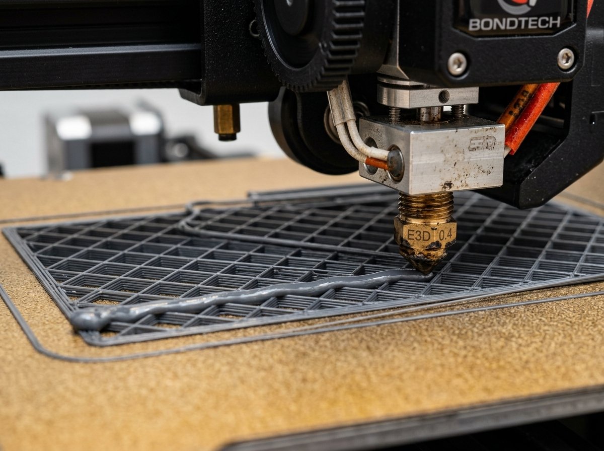
When high-speed printers move at speeds above 250 mm/s with accelerations exceeding 10,000 mm/s², the nozzle crossing over solid plastic grid intersections acts like a tiny speed bump. On tall or narrow prints, this mechanical impact can knock the part loose from the PEI bed sheet or cause stepper motors to skip steps, creating ruined prints.
Maker's Workshop Note
During a 12-hour print run of eSUN PETG on an Ender 3 V3 KE operating at 250 mm/s, Grid infill caused severe nozzle scraping noise starting around layer 80. The PETG accumulated on the nozzle tip from the intersection points, eventually depositing a burnt blob onto an outer wall. Switching the slicer profile to Gyroid infill at 18% completely eliminated nozzle scraping noise and yielded pristine outer perimeters on the next run without altering temperatures or flow ratios.
Practical troubleshooting steps to eliminate nozzle drag during printing:
- Switch to Non-Crossing Patterns: Select Gyroid, Rectilinear, or Cross Hatch in Orca Slicer, Bambu Studio, or PrusaSlicer.
- Calibrate Filament Extrusion Multiplier: Over-extrusion expands infill line width beyond slicer calculations, magnifying line intersection heights.
- Enable Z-Hop on Travel Moves: Set a minimal Z-hop (0.2 mm to 0.4 mm) during retracted travels to lift the hotend tip over internal structures.
- Adjust Infill Speed Multipliers: If keeping Grid infill, reduce infill travel speed to match outer wall speed to allow extruded lines time to settle flat.
Thermal Expansion and Volumetric Pressure Spikes
Beyond mechanical contact, printing grid infill at high volumetric flow rates introduces severe melt-zone pressure fluctuations inside the hotend. When the nozzle decelerates slightly to cross an existing line intersection, nozzle backpressure spikes momentarily. This pressure spike forces molten plastic to ooze sideways, compounding the height of the intersection bump on subsequent passes.
Amorphous filaments with higher thermal expansion coefficients—such as PETG, ABS, and ASA—exacerbate this phenomenon. As extruded PETG lines cool on the build plate, they swell slightly above the nominal layer height. When the nozzle completes a grid pass over a cooled intersection, it physically plows through the raised plastic. This causes cumulative plastic drag that increases progressively with part height.
In contrast, smooth sweeping infill paths like Gyroid allow the extruder motor to maintain steady extrusion pressure. Because volumetric flow rates remain constant throughout the infill layer pass, hotend pressure stays stable, preventing stringing blobs and under-extrusion gaps near wall boundaries.
Slicer Benchmarks and Material Usage Comparison
Evaluating slicing benchmarks across Orca Slicer and PrusaSlicer reveals how infill selection impacts filament weight and print time for a standard 100mm cube test model printed with 0.20mm layer height and 3 wall loops:
- 15% Grid Infill: Print Time: 1 hr 42 min | Filament Consumed: 112 grams. Fast linear passes, but audible nozzle rubbing during layer changes.
- 15% Gyroid Infill: Print Time: 1 hr 48 min | Filament Consumed: 108 grams. 6 minutes longer execution time, but completely silent toolhead travel and zero nozzle scraping.
- 15% Honeycomb Infill: Print Time: 2 hrs 14 min | Filament Consumed: 124 grams. Significantly longer print time due to frequent direction changes; higher mass due to dense hexagon wall intersections.
- 15% Adaptive Cubic: Print Time: 1 hr 39 min | Filament Consumed: 96 grams. Lowest material consumption while maintaining good structural rigidity near outer top surfaces.
- 15% Cross Hatch Infill: Print Time: 1 hr 41 min | Filament Consumed: 106 grams. Excellent print speed matching Grid performance without line-crossing nozzle collisions.
For most day-to-day functional projects, Gyroid infill represents the most dependable balance of multi-directional strength, smooth motion, and reliable print execution.
Frequently Asked Questions
Why does my 3D printer nozzle scratch against Grid infill?
Grid infill prints crossing lines on the exact same layer plane. At every point where two lines cross, double the volume of plastic is deposited. This creates tiny raised points of plastic that rub against the nozzle during subsequent passes, causing scratching sounds and potential print failure.
Is Gyroid infill really stronger than Grid infill?
Gyroid infill is stronger under multi-directional and shear forces because its 3D wave structure distributes load evenly across X, Y, and Z axes. Grid infill is strong under direct vertical or horizontal compression along its line paths, but splits easily when twisted or subjected to diagonal loads.
Which infill pattern is fastest for FDM printing?
Rectilinear and Grid are generally the fastest patterns because they consist of long straight extrusion passes with minimal direction changes. However, for complex or tall parts, the time saved by Grid infill is often lost if nozzle scraping causes layer shifts or print failures.
Does Gyroid infill cause printer vibration?
Gyroid infill moves the toolhead in smooth continuous curves rather than sharp right angles, which actually reduces sharp acceleration spikes. However, on machines with loose belts or uncalibrated resonance tuning, the rapid low-amplitude curving motion can induce frame hum. Tightening belts to ~110 Hz eliminates this resonant hum.
Can I print TPU with Gyroid infill?
Yes, Gyroid is one of the best infill patterns for flexible TPU filaments. Because its 3D sinusoidal structure acts like a uniform mechanical spring, TPU parts printed with Gyroid compress smoothly and bounce back without internal creasing or hollow pocket collapse.
References & External Sources
- OrcaSlicer Wiki & Calibration Documentation — Official guidelines on infill patterns and extrusion settings.
- Prusa Knowledge Base: Infill Patterns Explained — Detailed technical comparison of 2D and 3D infill geometries.
- Bambu Lab Wiki: Infill Pattern Selection Guide — Optimization advice for high-speed CoreXY printing.
- CNC Kitchen: Structural Infill Strength Testing — Empirical mechanical testing data for FDM infill patterns.
About the Author: Dinu Suciu
Dinu Suciu is an active 3D printing maker and technical writer specializing in FDM printer optimization, custom slicer profiling, and functional prototyping. Operating multiple CoreXY and Cartesian FDM printers in his workshop, Dinu tests material performance, hardware upgrades, and calibration techniques to help makers get reliable, high-precision results. Have questions about slicer settings or custom prototyping? Get in touch via the Contact Page.