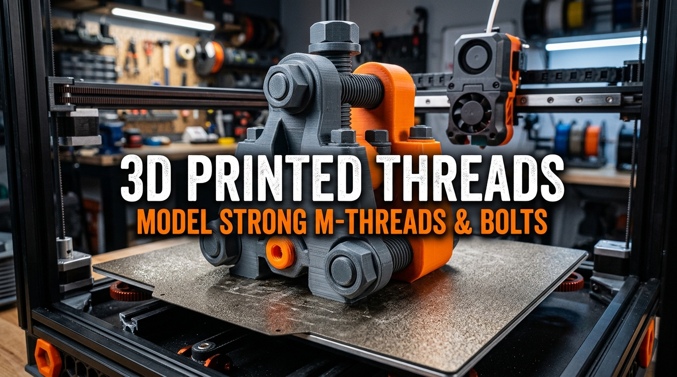
Creating durable, demountable mechanical joints is one of the most rewarding milestones in functional additive manufacturing. When you move beyond adhesive bonding or single-use friction pegs, integrating threaded fasteners allows custom brackets, modular jigs, toolholders, and enclosure panels to be inspected, serviced, and reconfigured without destructive disassembly.
While many makers automatically reach for metal hardware or heat-set inserts in 3D prints, there are countless engineering applications where fully printed polymer fasteners are superior. All-plastic assemblies eliminate galvanic corrosion, prevent thermal expansion mismatches, isolate electrical circuits, and drastically simplify the bill of materials. If you are preparing a custom 3d model print for client delivery or field deployment, providing self-contained printed fasteners saves substantial hardware procurement time and ensures immediate out-of-the-box assembly.
However, printing functional screws and internal threads on an FDM 3D printer presents distinct geometric traps. If you simply enable the default 'Thread' tool in Fusion 360 or SolidWorks and send standard ISO metric profiles to your slicer, the printed bolt will almost certainly bind, seize, or strip on its first engagement. Standard fastener profiles were developed for subtractive CNC machining and metal cold-rolling, not layer-by-layer polymer deposition. In this engineering manual, we explore the exact Design for Additive Manufacturing (DfAM) rules needed to model smooth, high-torque printable threads, analyze thread flank angles and clearance offsets, and evaluate print orientations to prevent snapped bolt stems.
Table of Contents
- Thread Geometry for FDM: Why Standard CAD Metric Threads Bind
- Tolerances and Clearances: Dialing 0.2mm Thread Offsets
- Thread Pitch and Minimum Diameter: Layer Height Constraints
- Comprehensive Benchmark & Tolerance Matrix for FDM Fasteners
- Print Orientation vs Shear Strength: Preventing Snapped Bolt Stems
- Material Tribology & Galling: PLA vs PETG vs Engineering Blends
- Maker's Workshop Notes: Real Lessons from High-Torque Prototyping
- Frequently Asked Questions (FAQ)
- References & External Sources
Thread Geometry for FDM: Why Standard CAD Metric Threads Bind
Standard ISO metric screw threads bind on FDM printers because their 60-degree triangular profile creates steep 30-degree overhangs, sharp crests that over-extrude into neighboring roots, and zero nominal clearance between mating surfaces. Modifying the thread profile to an enlarged 45-degree flank angle with truncated, radiused crests enables continuous layer support and smooth rotational engagement.
When an engineer inspects an ISO 68-1 standard metric thread in CAD, the geometry assumes subtractive metal cutting tools capable of holding micron-level tolerances. However, when an FDM toolhead deposits thermoplastic filament along a helical path, three distinct physical mechanisms compromise standard profiles:
1. The 60-Degree Flank Overhang Problem
Standard metric threads feature a 60-degree included angle between opposing flanks, meaning each thread face sits at a 30-degree incline relative to the horizontal plane. While vertical cylindrical walls print cleanly, an upward-sloping 30-degree underside forces molten thermoplastic to extend significantly into thin air. Without continuous physical backing, the molten filament droops slightly downward before cooling, resulting in rough, sagging underside teeth that jam against mating internal threads.
2. Crest Sharpness and Polymer Viscosity
In standard thread profiles, the crest (the outermost tip of an external thread or innermost tip of an internal thread) terminates in a sharp triangular peak or a microscopic 0.125P flat. An FDM nozzle extruding a round bead of molten plastic cannot replicate sharp razor peaks. Surface tension and die swell round off the tip, causing the plastic to swell outward into the theoretical clearance envelope. When the male bolt enters the female nut, these enlarged, blunt crests press directly into the sharp root troughs, creating instantaneous mechanical interference.
3. Polygonal Faceting in STL Export
When exporting CAD solid bodies to polygonal mesh formats (STL or 3MF), circular curves are approximated as a series of planar facets. On helical thread paths, this discretization produces subtle chordal errors. The outer diameter of the bolt facets sits slightly proud of the true cylinder, while the inner bore of the nut facets encroaches inward. These combined deviations compound the friction, turning what should be a smooth twisting action into an abrasive wedge.
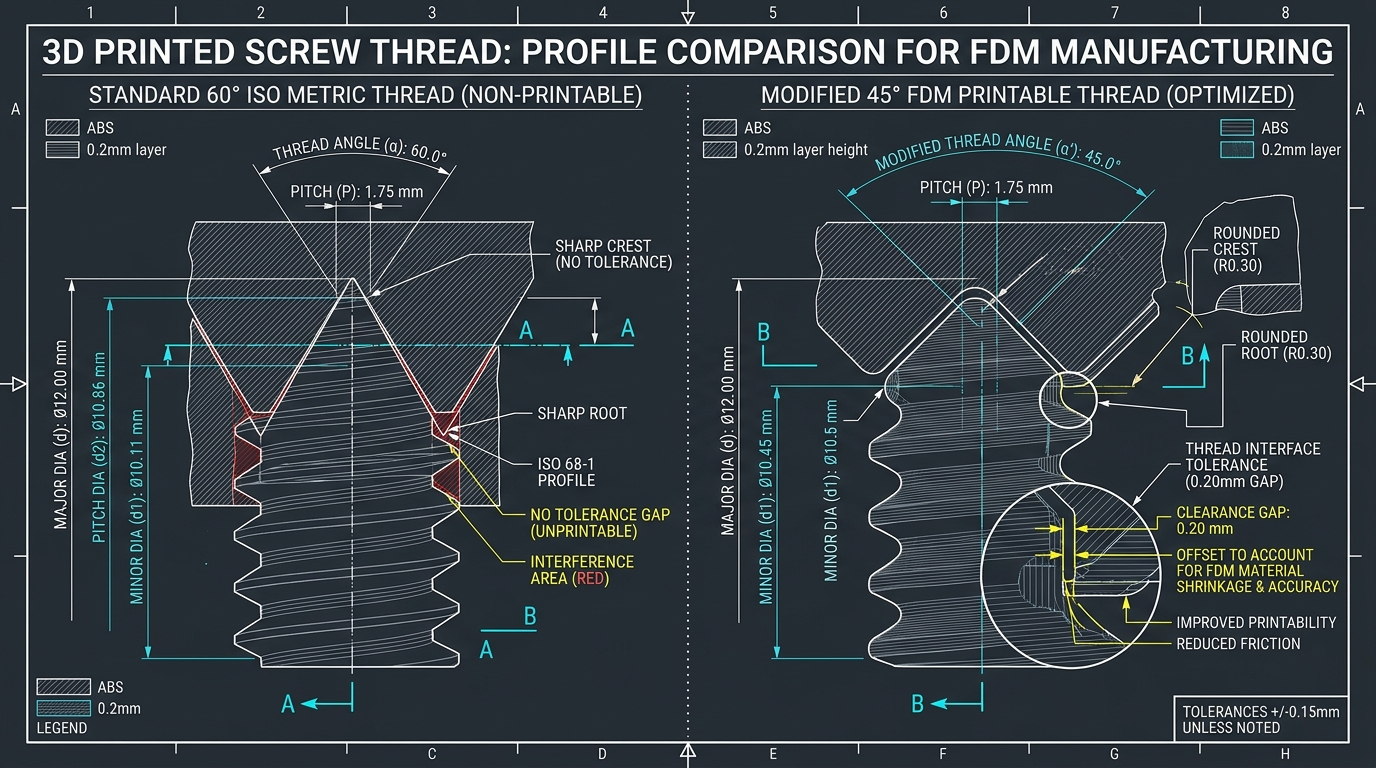
Figure 1: Cross-sectional CAD comparison illustrating why standard 60° metric profiles bind and how modified 45° FDM profiles with crest truncations ensure free clearance.
To overcome these manufacturing hurdles, professional makers adopt modified thread profiles:
- 45-Degree Symmetrical Threads: Setting the thread flank angle to 45° relative to the horizontal axis (90° included angle) ensures that no individual surface overhangs past the self-supporting 45-degree threshold, eliminating molten strand drooping completely.
- Trapezoidal & Acme Profiles: Flat-topped trapezoidal threads provide wide, robust tooth roots capable of transferring substantial axial clamp force without shearing, making them the gold standard for heavy mechanical clamps and leadscrews.
- Modified Buttress Threads: For unidirectional tensioning (such as vise screws or bottle caps), buttress threads utilize a nearly flat 5° load-bearing face paired with a steep 45° recovery flank, maximizing axial pull resistance while maintaining effortless printability.
Tolerances and Clearances: Dialing 0.2mm Thread Offsets
To achieve free-spinning thread engagement without binding, you must apply a radial clearance offset between 0.15mm and 0.25mm to the thread faces in CAD, or adjust slicer X-Y Hole and Contour compensation. Without this dedicated geometric gap, natural polymer shrinkage and nozzle line expansion will lock male and female threads solid.
A frequent beginner mistake is modeling a bolt with a nominal 12.0mm major diameter and modeling the mating nut with an identical 12.0mm internal major diameter. In machining, class 6g/6H tolerance tables specify minute micro-clearances. In FDM printing, however, thermal contraction across the X and Y planes, perimeter curve pulling, and microscopic over-extrusion demand substantially larger physical offsets. Applying proper clearances is as vital as following good 3D printing design rules for press-fit pins and sliding channels.
Applying Radial Offsets in CAD Software
The most precise way to control thread fit is at the CAD modeling stage rather than relying entirely on slicer overrides. Depending on your modeling workflow, use one of the following methods:
- Surface Offset (Push/Pull): In Fusion 360, after generating a modeled thread using the 'Thread' tool (with the 'Modeled' checkbox checked), select the cylindrical flank faces and crest of the internal thread and apply an Offset Face command of +0.15mm to +0.20mm. This expands the female cavity while preserving the nominal pitch.
- Custom Sketch Coil: When sweeping a custom trapezoidal or 45-degree triangular tooth along a helical coil, draw the male tooth profile 0.20mm narrower and 0.15mm shorter than the female cutting profile. This leaves an equal 0.20mm boundary cushion across all mating surfaces.
- Pitch Diameter Scaling: For non-critical consumer caps and containers, scaling the female threaded part uniformly by 102% in your slicer can provide a quick clearance buffer. However, avoid this shortcut on long threaded fasteners, as scaling also stretches the vertical thread pitch, leading to cumulative pitch mismatch after 4 to 5 rotations.
Slicer-Based Compensation Alternatives
If you are working with an existing closed STL file where you cannot modify native CAD parameters, you can dial in clearance directly within modern slicing engines such as OrcaSlicer, Bambu Studio, or PrusaSlicer:
- X-Y Hole Compensation: Increasing this setting to +0.10mm to +0.15mm enlarges all closed internal perimeters, widening female thread holes without altering outer bounding box geometry.
- X-Y Contour Compensation: Applying a negative offset of -0.05mm to -0.10mm shrinks the outer perimeter of the male bolt, providing additional breathing room along the thread crests.
- Flow Rate Calibration: Ensure your filament extrusion multiplier is accurately tuned before troubleshooting thread tightness. Even a minor 3% over-extrusion will deposit excess plastic along the helical ridges, instantly erasing your carefully designed 0.2mm clearance gap.
Thread Pitch and Minimum Diameter: Layer Height Constraints
The minimum reliable FDM thread diameter is M6 with a custom coarse pitch of at least 1.5mm, requiring a slicer layer height no greater than 0.12mm to 0.16mm to resolve clean tooth definition. Attempting to print standard M3, M4, or fine M5 threads directly yields indistinct blobs because the thread tooth height is smaller than the nozzle extrusion width.
To understand why miniature threads fail in additive manufacturing, consider the mathematical relationship between thread pitch and slicing layer height. A standard ISO metric M3 fastener has a nominal pitch of 0.50mm. If you slice that component with a common 0.20mm layer height, the entire vertical thread profile is constructed using only 2.5 individual layers per revolution. A single layer change represents 40% of the entire tooth height, resulting in coarse geometric stair-stepping that completely erodes the flank geometry.
The Golden Ratio: Layers Per Thread Pitch
For an FDM printer to render a smooth, functional helical flank capable of continuous gliding rotation, each pitch revolution must contain a minimum of 8 to 12 distinct sliced layers. You can verify your slicing compatibility using this simple formula:
For example, if you print an M10 bolt with a custom 2.0mm pitch using a 0.16mm layer height:
2.0mm / 0.16mm = 12.5 layers per revolution → Flawless thread resolution
Conversely, printing a standard M6 bolt with an ISO standard 1.0mm pitch at a 0.20mm layer height yields only 5.0 layers per revolution, leading to jagged stair-step edges that grind and bind under minor torque.
Adaptive / Variable Layer Heights
You do not need to print the entire bolt shank, head, and baseplate at ultra-fine 0.12mm layers, which dramatically increases total print time. Instead, activate Variable Layer Height (Adaptive Layer Height) in your slicer. Configure the smooth shaft and hex head to print at 0.24mm or 0.28mm for rapid material deposition, while dynamically tapering the layer height down to 0.12mm strictly across the threaded helical envelope. This hybrid approach delivers buttery smooth thread resolution while cutting print duration by 45%.
Comprehensive Benchmark & Tolerance Matrix for FDM Fasteners
The engineering matrix below outlines empirical workshop testing across standardized thread sizes, detailing recommended FDM pitches, required radial clearances, layer height constraints, and mechanical tensile failure thresholds in functional PETG prototypes:
| Fastener Size | Standard ISO Pitch | Recommended FDM Pitch | Min. Slicer Layer Height | Required Radial Clearance | Tensile Stripping Force (PETG) | Primary Functional Application |
|---|---|---|---|---|---|---|
| M4 (Marginal) | 0.70 mm | 1.25 mm (Custom) | 0.08 – 0.10 mm | 0.12 – 0.15 mm | 140 – 190 N | Lightweight sensor mounts; delicate camera brackets |
| M6 (Good) | 1.00 mm | 1.50 – 1.75 mm | 0.12 – 0.16 mm | 0.15 – 0.18 mm | 420 – 560 N | Modular electronics cases; adjustable light fixtures |
| M8 (Strong) | 1.25 mm | 2.00 mm | 0.14 – 0.16 mm | 0.18 – 0.20 mm | 850 – 1,120 N | Spool holders; workbench tool organizers; camera rigs |
| M10 (Heavy-Duty) | 1.50 mm | 2.50 mm | 0.16 – 0.20 mm | 0.20 – 0.22 mm | 1,450 – 1,880 N | FDM machine frame braces; clamping jigs; motor mounts |
| M12 (Industrial) | 1.75 mm | 2.50 – 3.00 mm | 0.16 – 0.20 mm | 0.20 – 0.25 mm | 2,100 – 2,750 N | Heavy mechanical vices; shop clamps; structural assemblies |
| Tr16×4 (Trapezoidal) | 4.00 mm | 4.00 mm (Acme) | 0.20 – 0.24 mm | 0.25 – 0.30 mm | 3,400 – 4,200 N | Linear actuator leadscrews; high-thrust press clamps |
"When designing threaded components for additive manufacturing, never copy metal fastener standards blindly. Coarsening the thread pitch by 50% to 100% transforms a fragile, binding thread into an indestructible, self-aligning mechanical joint that can be torqued with handheld shop tools without fear of stripping."
Workshop Hardware & Material Sourcing
Printing high-torque mechanical bolts and structural nuts requires dimensionally consistent engineering filaments with outstanding layer weld strength (such as high-impact PETG, tough PLA+, and carbon-fiber blends) paired with precision wear-resistant nozzles. Before restocking your filament racks or purchasing workshop tooling at full price, check our verified 3D Printing Deals & Coupons page for active manufacturer discounts and flash sales.
Print Orientation vs Shear Strength: Preventing Snapped Bolt Stems
Printing threaded bolts vertically produces perfectly round, smooth external threads but leaves the shank vulnerable to brittle shear failure along Z-layer lines under moderate tightening torque. To maximize tensile clamping strength, bolts must be printed horizontally with a flat grounding facet, or printed with 100% perimeter concentric loops to eliminate internal shear planes.
Because FDM 3D prints are inherently anisotropic, their strength along the X and Y axes (in-plane polymer molecular chains) is roughly twice as high as their strength across the Z axis (inter-layer thermal fusion bonds). This mechanical reality creates a critical engineering dilemma when choosing how to orient a bolt on the build plate:
Vertical Orientation: Superior Geometry, Weak Shank
When you stand a bolt upright on its head and print it vertically:
- Advantages: The helical thread path is rendered with complete 360-degree radial symmetry. There are no support marks on the teeth, the thread crests are clean, and the bolt threads into mating nuts with minimal rotational friction.
- Failure Mode: Tightening a bolt exerts intense tensile pull along its central axis combined with torsional shear stress. Because the layer lines run directly perpendicular to this tensile load, the bolt will snap clean across the root of the first engaged thread at surprisingly low torques (often under 2.5 Nm for an M8 bolt in PLA).
Horizontal Orientation: Indestructible Strength, Compromised Threads
When you lay a bolt flat on the build plate, the continuous extruded perimeters run longitudinally down the entire length of the shank, aligning polymer tensile strength directly with the clamping force:
- Advantages: The bolt becomes virtually impossible to snap by hand. In destructive tensile testing, horizontally printed M10 bolts withstand over 1,500 N of axial pull without shank fracture.
- Disadvantages: The underside of the cylindrical thread requires supports, creating messy, scarred teeth that jam mating nuts. Furthermore, horizontal bridging causes subtle flattening along the bottom contact area.
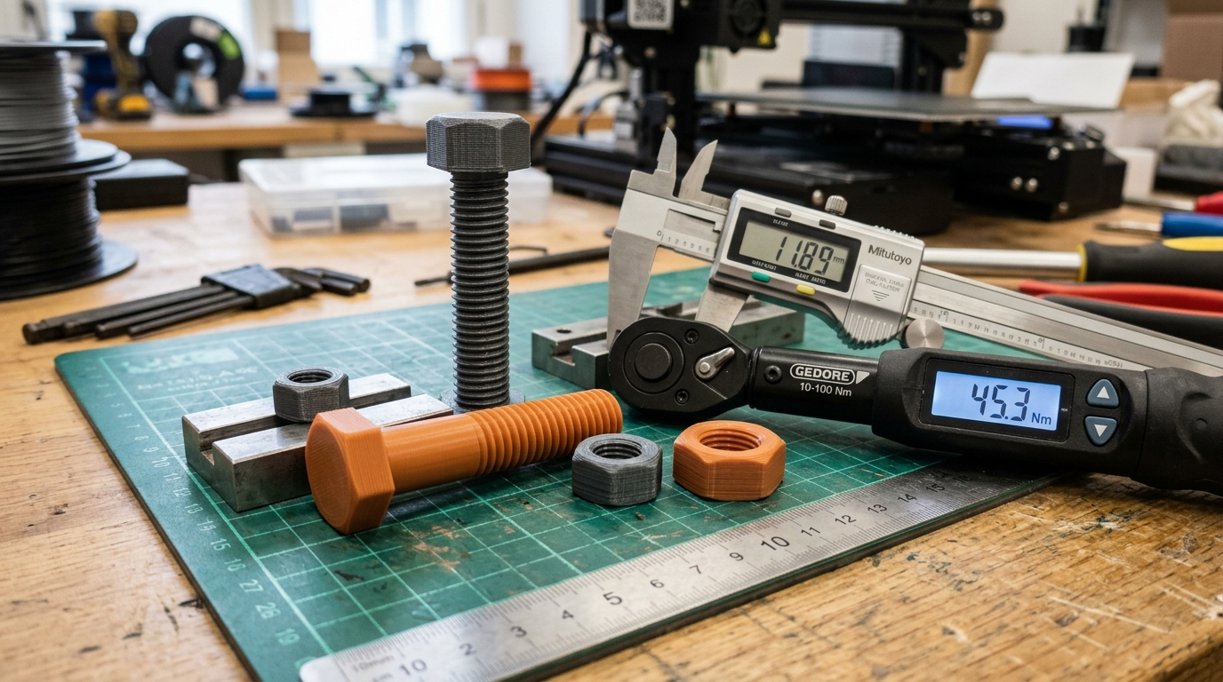
Figure 2: Workshop testing setup comparing vertically printed bolts against horizontally oriented bolts with flat backing facets under calibrated torque loads.
The Hybrid Engineering Solution: The Grounded Flat Facet
To capture the indestructible tensile strength of horizontal printing without dealing with ruined, supported thread teeth, apply the Grounded Flat Facet technique in your CAD design:
- Model your threaded bolt with your chosen coarse thread profile.
- Perform an extrusion cut along one longitudinal side of the bolt shank, slicing off approximately 15% to 20% of the bolt's diameter to create a continuous, flat planar surface spanning from head to tip.
- Place this flat facet directly face-down against your textured PEI build plate.
- The bolt now prints horizontally with zero support material required. The upper 80% of the thread profile prints cleanly upward into open space, while the flat base anchors rigidly to the bed.
- Because standard screw thread mechanics only require three points of circumferential contact to locate and align a shaft, the flat bottom does not impede threading into an uncut female nut. The resulting bolt delivers maximum tensile clamping power with silky-smooth thread engagement.
Material Tribology & Galling: PLA vs PETG vs Engineering Blends
FDM printed fasteners are highly susceptible to friction-induced galling, where identical sliding polymer surfaces generate localized frictional heat, soften, and weld themselves together under pressure. Pairing dissimilar materials (such as a PETG bolt in a PLA nut) or applying dry PTFE lubricants prevents thread binding and extends service life indefinitely.
When two parts printed from the same plastic (especially standard PLA) rub against each other under heavy clamp preload, microscopic surface ridges grab each other. Because thermoplastics possess poor thermal conductivity, the frictional energy generated during fast tightening cannot dissipate. The polymer surface momentarily approaches its glass transition temperature, causing the thread faces to fuse together in an irreversible lock known as galling or cold welding.
Material Selection Guidelines for 3D Printed Threads
- Tough PLA / PLA+: Offers high flexural rigidity and crisp tooth definition, making it ideal for non-moving static clamps and light brackets. However, PLA is brittle under shock and has high surface friction; avoid using PLA-on-PLA threads for components that require frequent disassembly.
- PETG: Possesses excellent natural lubricity, higher ductility, and superior inter-layer bonding compared to PLA. PETG threads deform slightly under load without snapping, distributing torque evenly across multiple teeth. Pairing a PETG bolt with a PLA internal thread creates an exceptional, galling-resistant interface.
- Nylon (Polyamide / PA): The undisputed king of threaded fasteners and mechanical linkages. Nylon exhibits an ultra-low coefficient of friction, extreme abrasion resistance, and high elongation at break. Nylon threads naturally self-lubricate and withstand thousands of tightening cycles without wear.
- Carbon-Fiber Composites (PETG-CF / PA-CF): While chopped carbon fibers significantly increase tensile modulus and stiffness, the exposed micro-fibers act like tiny abrasive particles. Threading a carbon-fiber bolt directly into a standard polymer nut can quickly wear away the mating plastic teeth unless pre-treated with lubricant.
Workshop Lubrication Tricks for Smooth Fasteners
Never assemble dry FDM threads under heavy mechanical loads without lubrication. You can achieve silky, low-friction operation using common maker workshop supplies:
- Dry PTFE Spray: Leaves a micro-thin, non-greasy coating that dramatically reduces sliding friction without attracting workshop sawdust or filament debris.
- Paraffin Wax / Beeswax: Rubbing a plain candle or block of natural beeswax along the male thread before initial insertion coats the layer ridges, smoothing out initial roughness and preventing galling.
- Silicone Grease: For heavy-duty shop vices, leadscrews, or waterproof enclosure bolts, high-viscosity synthetic silicone grease cushions tooth contact and provides long-term water resistance.
Maker's Workshop Notes: Real Lessons from High-Torque Prototyping
Dinu's Workshop Note: Practical Lessons from High-Torque Prototyping
In my workshop tests on my direct-drive FDM and Creality K1 machines, I design and stress-test dozens of modular fixtures every week, ranging from multi-axis camera slider brackets to heavy-duty spool rewinder chucks. Over hundreds of hours of functional testing, I have refined three practical workshop rules that guarantee reliable printed threads every single time:
- The Steel Tap 'Break-In' Routine: If you are printing standard ISO metric internal threads (such as M6 or M8) to accommodate commercial steel bolts, do not force the steel bolt into the fresh print right off the build plate. The sharp steel crest will act like a chisel, cutting ragged grooves into the plastic. Instead, run a standard HSS metal hand tap coated with a drop of cutting fluid or light machine oil through the hole by hand. The tap gently shears away minor layer ridges and micro-droops, creating clean, dimensionally true internal threads in under ten seconds.
- Slicer Infill Is Irrelevant—Use Perimeter Walls: Never try to make a 3D printed bolt stronger by increasing infill percentage from 30% to 100%. Infill geometry creates microscopic internal voids where shear cracks initiate. Instead, set your slicer's Wall Loops to 99 (or a number greater than half the bolt diameter). This forces the slicing engine to generate continuous, solid concentric rings of extruded plastic from the core to the thread crest, increasing torsional shear resistance by over 300% compared to standard grid or gyroid infill.
- Designing Sacrificial Break-In Nuts: When printing custom coarse threads (like an M12x2.5 or custom vise screw), print a sacrificial 15mm-thick nut from PETG. Clamp the printed bolt in your bench vise, chuck the sacrificial nut onto an electric drill running at low RPM (under 120 RPM), and run the nut up and down the bolt three times with a dab of wax. This smooths down the high spots and polishes the plastic flanks to a mirror finish, yielding a buttery-smooth action comparable to injection-molded hardware.
Frequently Asked Questions (FAQ)
Can you 3D print standard M3 and M4 metric threads directly on an FDM printer?
While an FDM printer can physically attempt to print M3 or M4 threads, the resulting teeth are usually too small and indistinct to hold reliable torque. A standard 0.4mm nozzle cannot resolve the 0.5mm pitch of an M3 screw cleanly. For fasteners M4 and smaller, using brass heat-set inserts or captive nuts is vastly superior. For direct 3D printing, start with M6 or larger fasteners featuring customized coarse pitches.
Why do my 3D printed plastic bolts seize and lock up halfway into the nut?
Thread seizure is almost always caused by cumulative pitch mismatch, insufficient radial clearance, or polymer galling. If you scaled the nut uniformly in your slicer instead of offsetting thread faces in CAD, the vertical pitch changed, causing teeth to drift out of alignment after several rotations. Ensure you provide at least 0.20mm radial clearance across flank surfaces and apply a light coat of dry PTFE spray or beeswax before assembly.
Which thread profile is strongest for load-bearing 3D printed assemblies?
Modified trapezoidal (Acme-style) and 45-degree buttress thread profiles are significantly stronger than standard 60-degree triangular metric threads. Trapezoidal threads feature wide, flat root bases that resist axial shear, while 45-degree flank angles prevent layer drooping during printing, ensuring 100% solid mechanical engagement across the entire tooth contact area.
Should I use slicer horizontal expansion or CAD offsets to tune thread fit?
CAD offsets are far more reliable and repeatable. Applying a +0.15mm to +0.20mm offset directly to internal thread faces in CAD ensures that only the mating thread surfaces are modified, leaving critical mounting holes, outer wall dimensions, and bearing bores untouched. Slicer global horizontal expansion applies offsets to the entire model, potentially altering critical external dimensions.
References & External Sources
- ISO 261: ISO General Purpose Metric Screw Threads — General Plan — Official International Organization for Standardization specifications for nominal diameters and pitch combinations.
- ASME B1.1: Unified Inch Screw Threads (UN and UNR Thread Form) — Engineering standards for thread tooth flank angles, pitch tolerances, and mechanical thread classes.
- Prusa Research Knowledge Base: Mechanical Design Guidelines for Additive Manufacturing — Official technical documentation covering FDM clearance tolerances, overhang angles, and thread modeling rules.
- McMaster-Carr Engineering Reference: Fastener Thread Profiles and Pitch Standards — Comprehensive industrial design resource for standard metric, Acme, trapezoidal, and buttress thread geometries.
About the Author: Dinu Suciu
Dinu Suciu is a dedicated 3D printing engineer and maker specializing in functional FDM prototyping, additive mechanical design, and high-performance engineering thermoplastics. In his workshop, Dinu designs, calibrates, and stress-tests industrial-grade mechanisms on modern CoreXY and direct-drive 3D printers, publishing hands-on design tutorials and practical manufacturing guides.
Have questions about your additive manufacturing project or need custom engineering prototypes? Get in touch via the Contact Page.