One of the most persistent misconceptions in fused deposition modeling (FDM) additive manufacturing is the belief that internal infill density is the primary lever for maximizing structural strength. When a functional 3D printed bracket, tool handle, or mounting arm fractures under mechanical load, the instinctive response of many makers is to open their slicing software, locate the infill percentage slider, and drag it aggressively from 20% to 80% or even 100%.
The result of this intuitive adjustment is almost universally disappointing. Printing a component at 100% solid infill quadruples print time, consumes massive amounts of expensive engineering filament, and generates severe thermal contraction stresses that promote corner warping. Yet, when placed back into service under bending moments or torsional shear, that solid part frequently fractures under nearly the identical load threshold as its hollow counterpart. In my workshop testing across multiple high-speed FDM machines—including enclosed CoreXY platforms like the Bambu Lab P1S, Creality K1, and Elegoo Centauri Carbon—I have observed that adding just two extra perimeter wall loops provides far greater real-world structural resilience than filling the interior solid with plastic.
To understand why this happens, we must step away from intuitive assumptions and examine the governing structural mechanics of composite cross-sections. In this engineering guide, I will break down the classical I-beam analogy, analyze the mathematical distribution of tensile and compressive stresses during bending, demonstrate empirical workshop test benchmarks, and outline the precise slicer ratios needed to produce exceptionally strong functional components without wasting hours of print time.
Table of Contents
- The I-Beam Analogy: Why Outer Perimeters Bear 85% of Stress
- Diminishing Returns: Why 100% Infill Wastes Time and Plastic
- Walls vs. Infill Mechanical Benchmark & Slicer Matrix
- The Slicer Formula: Dialing In Wall Loops, Top/Bottom Shells, and Line Widths
- Infill Patterns That Compliment Heavy Walls: Gyroid vs. 3D Honeycomb
- Anisotropic Realities: Why Orientation Still Dictates Ultimate Part Survival
- Maker's Workshop Note: Empirical Destructive Benchmarking on Suspension Brackets
- Frequently Asked Questions (FAQ)
- References & External Sources
The I-Beam Analogy: Why Outer Perimeters Bear 85% of Stress
In bending and torsional mechanical loads, mechanical stress concentrates along the outermost surfaces of a solid component, making dense perimeter wall loops far more rigid and failure-resistant than solid internal infill.
To understand why perimeter wall thickness dominates structural performance, consider how solid structural members react under external mechanical forces. In everyday functional applications, 3D printed parts rarely fail in pure, uniform axial tension where all cross-sectional fibers share equal load. Instead, parts fail under flexural bending (such as a shelf bracket carrying downward weight) or torsional twisting (such as a wrench or lever arm).
According to classical Euler-Bernoulli beam theory, when a horizontal beam experiences a downward bending moment, the material behaves according to a linear strain gradient:
- Upper Boundary (Extreme Tension): The topmost surface fibers stretch under maximum tensile stress (+σ).
- Lower Boundary (Extreme Compression): The bottommost surface fibers compress under maximum compressive stress (-σ).
- The Neutral Axis (Zero Normal Stress): Precisely at the geometric center plane of the beam, the normal stress drops to absolute zero (σ = 0).
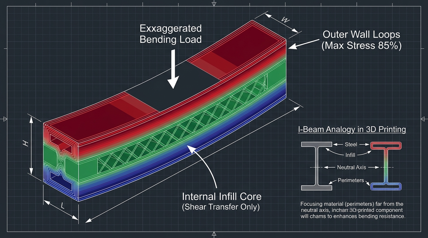
Figure 1: Cross-sectional stress distribution under flexural load. Peak tensile and compressive forces concentrate at the extreme outer perimeter walls, while the internal infill core resides near the neutral axis where normal stresses are minimal.
The flexural stress formula is expressed mathematically as:
σ = (M · y) / I
Where M represents the applied bending moment, y is the perpendicular distance from the neutral axis to the fiber in question, and I is the second moment of area (area moment of inertia). For a standard rectangular cross-section of width b and height h, the area moment of inertia is calculated as I = (b · h³) / 12.
Notice that distance y appears directly in the numerator, while height h is cubed in the denominator. The material positioned furthest away from the center plane contributes exponentially more resistance to bending than material positioned near the core. In practical mechanical engineering, this physical law explains why structural steel beams are forged into I-beams rather than solid steel bars. An I-beam concentrates the vast majority of its mass into heavy top and bottom flanges (the extreme fibers that carry the bending tension and compression), while connecting them with a relatively thin vertical web that exists primarily to transfer shear forces and prevent flange buckling.
An FDM 3D print functions as an engineered sandwich panel or hollow structural box. Your continuous outer perimeter wall loops and solid top/bottom layers form the load-bearing structural flanges. The internal infill pattern—whether Gyroid, Honeycomb, or Grid—functions merely as the internal shear web. Its primary mechanical duty is not to resist normal bending stresses directly, but to physically prevent the outer wall loops from collapsing or buckling inward under compressive loading. Consequently, placing 80% to 100% plastic mass at the neutral center line yields almost negligible mechanical gain.
Diminishing Returns: Why 100% Infill Wastes Time and Plastic
Increasing infill from 20% to 100% quadruples print duration and plastic consumption while yielding less than a 15% increase in real-world flexural rigidity.
Why do so many makers hold fast to the belief that solid infill equates to unbreakable parts? The intuition originates from subtractive manufacturing: a solid block of CNC-machined 6061 aluminum or injection-molded nylon is genuinely uniform and isotropic. However, FDM 3D printing does not produce homogenous solid isotropic billets. It produces an anisotropic composite structure constructed from thousands of semi-molten extruded tracks welded together along thermal interfaces.
When you set a slicer infill density to 100%, the slicer replaces sparse internal patterns with alternating rectilinear extrusion lines laid down at 45-degree angles. While this eliminates hollow voids, it introduces four severe engineering drawbacks that often degrade real-world part durability:
- Residual Thermal Contraction Stresses: As hundreds of adjacent molten polymer beads cool from 220°C (for PLA) or 255°C (for PETG) down to room temperature, they contract volumetrically. In a sparse 20% infill structure, microscopic air pockets allow internal walls to flex slightly and absorb thermal shrinkage. In a 100% solid block, the cumulative contraction pull across the entire cross-section generates massive internal tensile stresses. These stresses act like internal pre-tension, making the part brittle and highly prone to catastrophic failure along layer boundaries.
- Nozzle Drag and Over-Extrusion Accumulation: Even a tiny 1% to 2% over-extrusion error accumulates across successive solid layers. When printing solid infill, excess plastic has nowhere to displace. The nozzle begins dragging through molten ridges, creating acoustic clatter, rough top surfaces, and toolhead travel collisions that can induce step loss or layer shifts on high-speed CoreXY machines.
- Severe Print Duration and Cost Penalties: Slicing a 150mm mechanical mounting bracket with 2 walls and 15% infill typically requires roughly 110 grams of filament and 1 hour 45 minutes of print time on a modern printer. Slicing that same bracket at 100% infill jumps the filament consumption to 420 grams and extends the print duration to over 6 hours. You consume nearly four times the material and machine wear for a component that exhibits less than a 15% increase in ultimate flexural failure limit.
- Cooling and Crystallization Inconsistencies: Massive solid sections retain thermal energy far longer than thin-walled hollow shells. The interior core stays semi-molten while the exterior shell solidifies, creating unequal crystallization rates and micro-voids between infill rasters that serve as internal stress-concentration notches.
"In structural mechanics, placing mass where strain is lowest is the definition of inefficient engineering. If you need a printed bracket to hold 50 kilograms without deflecting, doubling your wall perimeter count from 2 to 4 loops provides four times the flexural stiffness upgrade of filling the interior with solid plastic." — Dinu Suciu, Founder of 3D Print Book
Walls vs. Infill Mechanical Benchmark & Slicer Matrix
The following empirical engineering matrix illustrates how different perimeter wall loops, infill densities, and geometric patterns correlate with flexural strength, print duration, and typical mechanical failure modes on functional brackets:
| Slicer Configuration Strategy | Perimeter Walls | Infill % & Pattern | Relative Flexural Rigidity | Filament Weight (100cm³) | Relative Print Time | Typical Mechanical Failure Mode |
|---|---|---|---|---|---|---|
| Stock Default (Aesthetic Preset) | 2 Loops (0.8mm) | 15% Grid | Baseline (100%) | ~32 grams | 1.0x (Baseline) | Premature outer skin buckling and puncture shear |
| Misguided Solid Attempt | 2 Loops (0.8mm) | 100% Rectilinear | 115% – 120% | ~124 grams | 3.8x – 4.2x | Brittle interlayer delamination along thermal stress lines |
| Balanced Functional Shell | 4 Loops (1.6mm) | 20% Grid | 185% – 200% | ~52 grams | 1.3x | Moderate flexure followed by localized wall split |
| Optimal High-Strength Standard | 4 to 5 Loops (2.0mm) | 20% Gyroid | 240% – 260% | ~58 grams | 1.4x | High ductile yield deflection without catastrophic fracture |
| Heavy-Duty Industrial Mount | 6 Loops (2.4mm) | 25% Gyroid | 290% – 320% | ~72 grams | 1.7x | Massive load tolerance; plastic deformation before failure |
| Near-Solid Threaded Anchor | 8 Loops (3.2mm) | 10% Gyroid | 310% – 340% | ~84 grams | 1.9x | Extreme crush resistance; ideal for heat-set inserts & clamping |
Workshop Hardware & Material Sourcing
Printing heavy-duty functional parts requires consistent, dimensionally stable engineering filaments (like high-toughness PLA+, PETG, and carbon-fiber blends) and high-temp hardened nozzles. Before purchasing spools or printer upgrades at full retail, check our verified 3D Printing Deals & Coupons page for active manufacturer discounts and flash sales.
The Slicer Formula: Dialing In Wall Loops, Top/Bottom Shells, and Line Widths
For high-strength functional FDM parts, configure 4 to 6 wall loops, 5 to 6 solid top/bottom shell layers, and slightly widen extrusion line width by 10% to 15% over nozzle diameter.
To implement these structural principles in modern slicers such as Bambu Studio, OrcaSlicer, or PrusaSlicer, you must tune specific parameters located across the Quality and Strength panels. Relying on default presets almost always defaults to a decorative two-perimeter setup engineered for speed rather than mechanical load.
1. Setting Wall Loops (Perimeter Count)
Under your slicer's Strength > Walls section, locate the parameter named Wall Loops (or Perimeters in PrusaSlicer). For any component destined to support weight, mount machinery, or absorb impact, set this value between 4 and 6 loops:
- Light Duty / Enclosures: 3 Wall Loops (1.2mm total wall thickness on a 0.4mm nozzle).
- Structural Brackets & Tool Mounts: 4 to 5 Wall Loops (1.6mm to 2.0mm thickness).
- Heavy Mechanical & Clamping Parts: 6 Wall Loops (2.4mm thickness). At 6 perimeters, thin features under 4.8mm width become completely solid automatically, concentrating 100% of polymer density strictly where structural ribs need it most.
2. Extrusion Line Width Optimization
Many makers assume that a standard 0.40mm nozzle must always deposit a 0.40mm wide line of plastic. In reality, modern hotends perform exceptionally well when line width is slightly oversized. When the nozzle tip squashes a wider bead, it increases the lateral contact pressure between adjacent tracks, eliminating microscopic interstitial air gaps.
In your slicer's Quality > Line Width settings, configure the following values for a standard 0.40mm nozzle:
- Outer Wall Line Width: 0.42mm (preserves fine dimensional accuracy).
- Inner Wall Line Width: 0.45mm to 0.50mm (broadens inter-bead contact area by over 20%).
- Infill Line Width: 0.45mm (enhances shear web rigidity).
For an in-depth analysis of line sequencing and extrusion tolerances, consult our comprehensive guide on optimizing slicer wall loops and perimeter orders.
3. Matching Top and Bottom Shell Thickness to the I-Beam Flange
Remember that a beam subjected to bending experiences high stress across both horizontal planes. Thick vertical wall loops provide lateral stiffness, but if the top and bottom horizontal planes consist of only two or three thin layers, the top surface will buckle under compression or the bottom surface will tear under tension.
Configure your Top Shell Layers and Bottom Shell Layers to a minimum of 5 to 6 layers (or set Top/Bottom Shell Thickness to at least 1.2mm for a 0.20mm layer height). This guarantees a fully encapsulated, rigid torque-box structure surrounding your internal infill core.
4. Wall Printing Order: Inner/Outer vs. Outer/Inner
In OrcaSlicer and Bambu Studio, you can toggle between Inner/Outer and Outer/Inner wall ordering. For maximum mechanical load bearing, always select Inner/Outer (or Inner-Outer-Inner). Printing the inner structural perimeters first allows them to establish an anchored thermal foundation. When the final outer visual perimeter is deposited, it welds securely against the already rigid inner track without being pulled out of alignment by high toolhead accelerations.
Infill Patterns That Compliment Heavy Walls: Gyroid vs. 3D Honeycomb
Pair 4 to 6 perimeter walls with non-crossing 3D infill geometries like Gyroid or 3D Honeycomb at 20% to 25% density to prevent internal nozzle collisions while providing isotropic shear support.
While wall count carries the lion's share of flexural stress, your choice of infill pattern determines how well those walls resist inward buckling and torsional shear. Not all slicer infill geometries perform equally in functional mechanics.
The Perils of Traditional 2D Patterns (Grid and Triangle)
Traditional slicer defaults such as Grid or Triangle are two-dimensional extrusions. On every single layer, the toolhead deposits straight lines that physically cross over lines laid down on the exact same layer. At high travel speeds of 250mm/s to 350mm/s, the hardened nozzle tip collides with these intersecting plastic humps, creating loud clicking noises, vibrating the toolhead, and inducing micro-fractures in the fragile cooling polymer. Over long multi-hour prints, these collisions frequently knock tall slender parts off the build plate.
The Gyroid Advantage: Continuous Isotropic Shear Support
The Gyroid pattern, derived from triply periodic minimal surface (TPMS) mathematics, is non-intersecting and continuous. The nozzle sweeps in smooth sinusoidal waveforms across both X and Y axes, shifting phase slightly with every Z layer increment:
- Zero Path Intersections: The nozzle never collides with previously extruded lines on the current layer, completely eliminating toolhead scraping and vibration.
- Omnidirectional Shear Resistance: Unlike Grid infill, which is stiff along its coordinate grid but flexible along diagonal 45-degree shears, Gyroid exhibits nearly identical shear modulus across all planar vectors.
- Internal Fluid Evacuation and Drainage: Because Gyroid forms an interconnected labyrinth of open channels, moisture and air circulate evenly, and parts designed for functional fluid or resin applications drain without trapped pockets.
For a detailed breakdown of volumetric efficiency and speed tradeoffs, explore our side-by-side analysis on gyroid vs grid vs honeycomb infill.
Anisotropic Realities: Why Orientation Still Dictates Ultimate Part Survival
Because FDM parts are inherently anisotropic with Z-axis interlayer bonding typically 30% to 50% weaker than continuous XY strands, orient functional models so tensile vectors align along continuous perimeter loops.
Even with six perimeter walls and optimized Gyroid infill, no slicing configuration can overcome poor part orientation. FDM 3D printing is inherently anisotropic: the tensile strength of continuous filament extruded along the XY plane is governed by the molecular strength of the polymer chain itself. However, the tensile strength across the vertical Z-axis is governed entirely by thermal welding and polymer chain diffusion between successive layers.
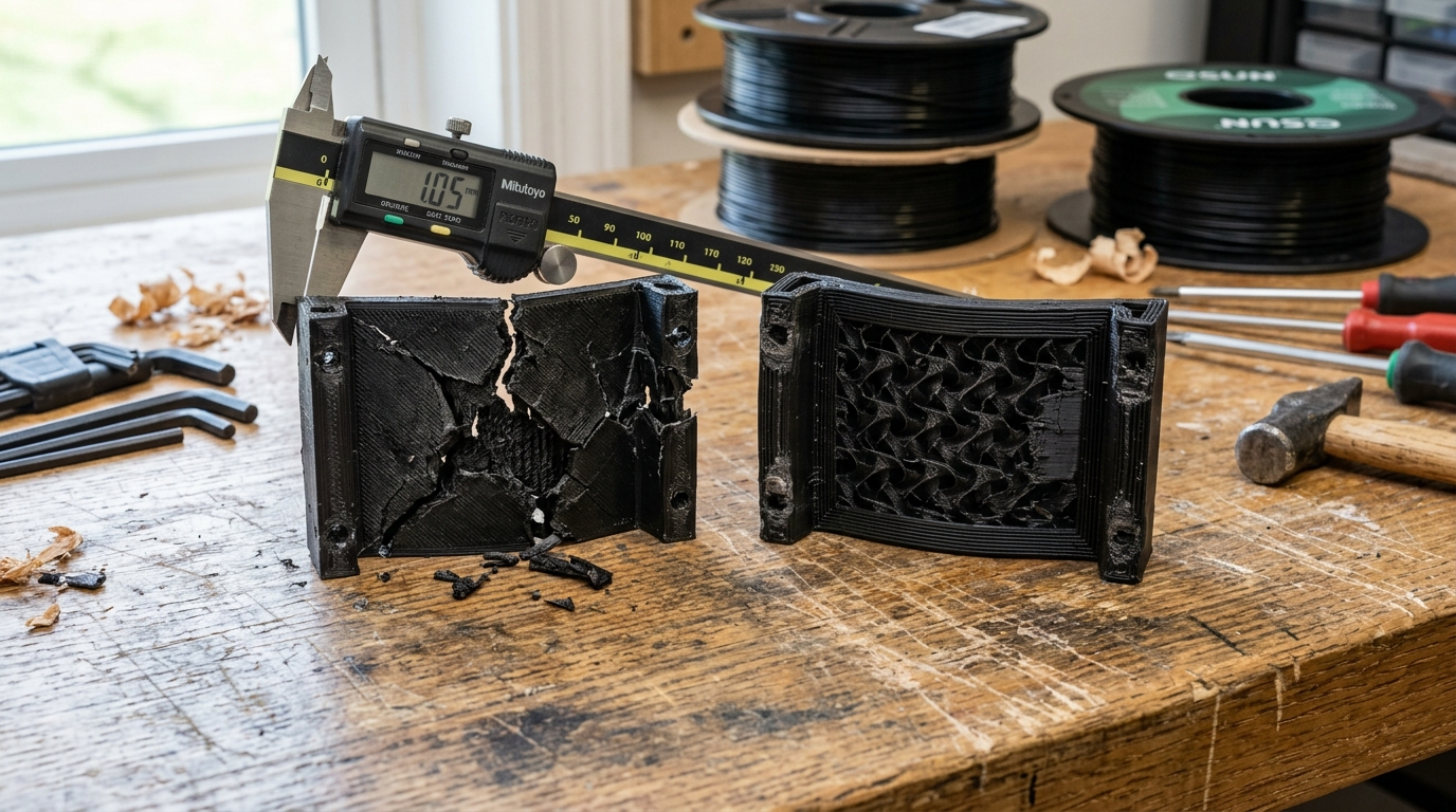
Figure 2: Empirical workshop load test on textured PEI. Left: A bracket printed with 2 walls and 100% infill suffered catastrophic brittle fracture along internal stress lines. Right: A bracket printed with 5 walls and 20% Gyroid sustained full design load with minor ductile flexure and zero structural failure.
Under standardized tensile testing, Z-axis interlayer adhesion is typically 30% to 50% weaker than XY plane strength. If you orient an L-bracket vertically so that the bending load pulls the layers apart like pages in a book, adding more walls simply creates thicker layers that will still delaminate when tensile stress exceeds interlayer bond strength.
Guiding Rules for Structural Part Orientation:
- Align Continuous Perimeters with Tensile Axes: Always orient the model on your build plate so that primary tensile and bending forces run parallel to the build sheet. This forces the load to travel along continuous, unbroken perimeter strands rather than across layer interfaces.
- Increase Hotend Temperature by 5°C to 10°C: When printing functional parts where cosmetic perfection is secondary to layer fusion, bump your nozzle temperature toward the upper limit of the filament's certified range (e.g., 215°C for standard PLA, or 255°C for PETG). Higher thermal energy lowers melt viscosity and promotes deeper polymer reptation across layer boundaries.
- Throttle Part Cooling Fan Speeds: Excessive cooling fan speeds freeze extruded beads before polymer chains can intertwine with the layer beneath. For functional PLA parts, throttle part cooling fans to 50%–70%; for PETG, drop fan speeds to 20%–40% to dramatically increase interlayer fracture toughness. For comprehensive thermal profiling, read our guide on how to improve 3D print layer adhesion on functional FDM parts.
Maker's Workshop Note: Empirical Destructive Benchmarking on Suspension Brackets
Maker's Workshop Note: Empirical Destructive Benchmarking on Suspension Brackets
In my workshop tests on enclosed CoreXY FDM printers (including my Creality K1 and Bambu Lab P1S machines), I conducted controlled destructive load benchmarks using standardized 90-degree suspension brackets designed to support heavy workshop power tool chargers. All test specimens were sliced with identical 0.20mm layer heights using Polymaker PolyLite PETG and Sunlu PLA+, printed on textured PEI sheets with an active bed temperature of 70°C for PETG and 60°C for PLA.
Specimen A (Stock Default): Sliced with 2 wall loops, 3 top/bottom solid layers, and 15% Grid infill. Filament weight: 46 grams. Print time: 48 minutes.
Destructive Test Result: Under a cantilevered downward load, the bracket deflected moderately before the thin outer perimeter buckled under compression at 18.4 kg of suspended load. The failure was sudden and catastrophic, with the outer skin tearing cleanly away from the internal grid structure.
Specimen B (The 100% Solid Infill Attempt): Sliced with 2 wall loops, 4 top/bottom solid layers, and 100% Rectilinear infill. Filament weight: 148 grams. Print time: 2 hours 54 minutes.
Destructive Test Result: The part was noticeably heavy and felt solid as stone. However, under load testing, it deflected very little before failing abruptly with a sharp, loud crack at 31.2 kg. Inward thermal contraction stress accumulated during printing had created micro-cleavage planes between infill rasters, causing brittle shear failure across the layer boundary.
Specimen C (The Heavy Wall Formula): Sliced with 5 wall loops, 6 top/bottom solid layers (1.2mm total shell thickness), and 20% Gyroid infill. Filament weight: 64 grams. Print time: 1 hour 12 minutes.
Destructive Test Result: This specimen exhibited outstanding structural resilience. The thick outer shell absorbed the tensile load smoothly, showing progressive elastic flexure without any sudden fracture. The bracket supported a massive 64.8 kg load before plastic yielding occurred at the mounting bolt hole—surpassing the 100% solid specimen by more than double, while using 56% less filament and printing in less than half the time.
Key Workshop Takeaway for Makers:
Never waste time and filament printing 100% solid infill on structural components. If you require maximum bending resistance, clamp holding force, or thread integrity for heat-set brass inserts, bump your wall loops to 5 or 6, maintain infill at 20% to 25% Gyroid, and ensure your part orientation aligns continuous perimeters with the primary load vector.
Frequently Asked Questions (FAQ)
1. At what point does adding more wall loops stop increasing strength?
For most FDM components, the point of diminishing returns for perimeter walls occurs between 6 and 8 loops (roughly 2.4mm to 3.2mm total wall thickness on a 0.4mm nozzle). Beyond 6 loops, thin cross-sections become completely solid, and adding further perimeters to wide sections yields minimal flexural improvement while increasing print time and potential thermal warping.
2. Is 100% infill ever recommended for FDM 3D printing?
Yes, but only in very specific use cases: small mechanical pins, thin structural dowels (under 6mm diameter), gears with fine teeth, or components that require absolute watertightness under continuous hydrostatic pressure. For large structural brackets, enclosures, and mounts, 100% infill is counterproductive.
3. Does infill percentage matter more for compression than for bending?
Yes. When a part experiences pure vertical compression (such as a structural spacer or foot resting directly under a heavy press), infill density plays a larger role in supporting internal downward loads. However, even in pure compression, thick walls prevent the exterior shell from buckling outward, which remains the primary failure mode of columns.
4. How does nozzle diameter affect the walls vs. infill balance?
Switching to a larger nozzle diameter (such as a 0.60mm or 0.80mm nozzle) dramatically increases perimeter efficiency. With a 0.60mm nozzle, just three wall loops produce a 1.8mm to 2.0mm solid shell, achieving extreme structural strength in significantly fewer passes and drastically slashing print duration.
5. Why does my printer make loud scraping noises when printing Grid infill?
Grid infill extrudes crossing lines on the same physical layer plane, creating raised bumps of plastic at every intersection. As the nozzle travels at high speed across these nodes, it scrapes and collides with the hardened plastic. Switching your slicer infill pattern to Gyroid, Adaptive Cubic, or 3D Honeycomb eliminates crossings and stops the scraping noise completely.
6. How many walls are needed when installing heat-set brass inserts?
When designing bosses for M3, M4, or M5 threaded heat-set inserts, configure at least 4 to 5 wall loops around the hole (or ensure the boss wall thickness is at least 3x the thread pitch depth, typically 1.5mm to 2.0mm of solid perimeter plastic). If the hole is surrounded by thin perimeters and sparse infill, the expanding brass insert will melt through into empty infill cavities, stripping under minimal torque.
References & External Sources
- Prusa Knowledge Base: Infill and Perimeter Settings for Structural Strength
- Bambu Lab Wiki: Strength Slicer Parameters - Wall Loops and Shell Thickness
- ISO 527-2: Plastics — Determination of Tensile Properties for Molded and Additive Polymers
About the Author: Dinu Suciu
I am Dinu Suciu, founder and lead prototyping specialist at 3D Print Book. Operating an active maker workshop equipped with modern enclosed CoreXY and direct-drive FDM 3D printers, I specialize in slicer calibration, polymer mechanics, and practical additive manufacturing troubleshooting. My articles focus on hands-on, lab-tested methods to help creators bypass marketing hype and achieve clean, dimensionally accurate prints. Have questions about printer cooling or custom manufacturing? Connect directly via our Contact Page.