




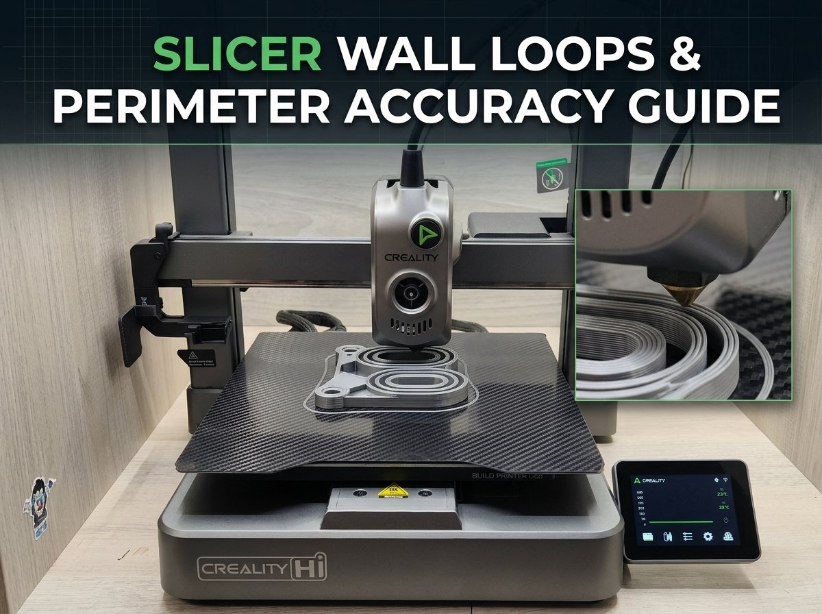
Achieving predictable tolerances on functional FDM 3D printed parts often determines whether mechanical assemblies slide together smoothly or jam during press-fit installation. When printing press-fit bearing seats, linear rail mounts, M3 threaded inserts, or interlocking enclosure tabs, minor variations in wall loop sequencing and extrusion compensation can shift critical dimensions by 0.15mm to 0.30mm.
While many makers focus primarily on bed leveling or hotend temperature when troubleshooting dimensional inaccuracies, the sequence in which your slicer extrudes perimeter wall loops plays an equally vital role. Molten thermoplastic behaves dynamically during extrusion: as hot polymer leaves the nozzle orifice, internal viscoelastic stress release causes thermal swell, followed by volumetric shrinkage as the bead cools. Managing how adjacent wall loops anchor to each other during this thermal transition is fundamental to improving 3D printer tolerance.
This technical guide breaks down the physical mechanisms behind wall loop deposition in modern slicers such as OrcaSlicer, Bambu Studio, and PrusaSlicer. We will examine perimeter order configurations, wall generator engines (Arachne vs. Classic), Precise Wall smoothing algorithms, arc fitting (G2/G3 moves), and fine-tuning X/Y Hole and Contour compensation parameters to produce reliable, high-precision engineering parts.
Table of Contents
- Inside-Out vs. Outside-In Wall Ordering
- Precise Wall Algorithms and Arc Fitting (G2/G3)
- Calibrating X/Y Hole and Contour Compensation
- Extrusion Width and Layer Height Tolerances
- Z-Seam Placement and Retraction Blobs
- Experimental Calibration Protocol
- Frequently Asked Questions (FAQ)
- References & External Sources
Inside-Out vs. Outside-In Wall Ordering: Thermal Shrinkage and Surface Accuracy
Wall loop sequence defines whether molten plastic expands outward or contracts inward as perimeters solidify. Printing inner perimeters before outer perimeters (Inside-Out order) anchors the final visible wall against established, cooling geometry, minimizing outward thermal swell and producing superior dimensional consistency for external part boundaries.
To understand why perimeter order affects physical part dimensions, consider how molten filament behaves when extruded into open space versus against an adjacent wall bead:
- Outside-In (Outer/Inner Wall Order): When the slicer extrudes the outermost perimeter first, the bead rests unsupported on the outer side and touches only the lower layer underneath. As the hot bead exits the nozzle tip, internal fluid pressure forces the plastic to expand sideways in both directions. When subsequent inner wall loops are extruded immediately afterward, they press outward against the still-soft outer perimeter, distorting the exterior boundary outward and increasing overall part width.
- Inside-Out (Inner/Outer Wall Order): When inner perimeters and infill are printed first, they form a solid internal structural foundation that cools for several seconds. When the printer subsequently extrudes the outer perimeter, the outer bead presses against a rigid inner wall. Thermal expansion is constrained inward toward the part core, ensuring the outer wall boundary matches the exact toolpath coordinates defined by the sliced STL geometry.
- Inner/Outer/Inner Sandwich Order: Available in advanced slicer profiles, this three-loop sequence extrudes an middle inner loop first, followed by the outer visible loop, and finishes with the innermost loop. This approach offers a balanced compromise between exterior surface smoothness and mechanical overhang overhang stability.
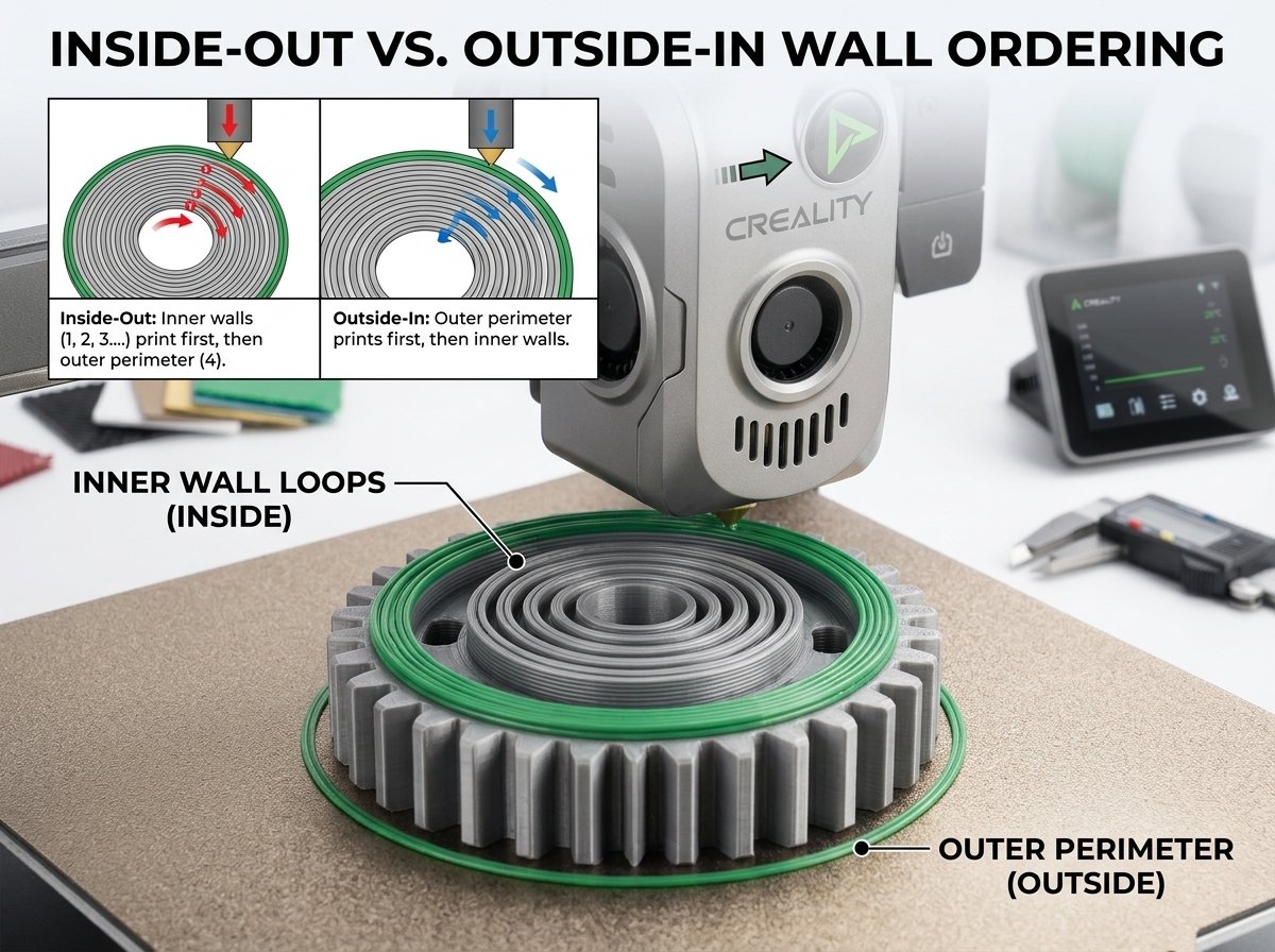
While Outside-In wall order is sometimes selected for cosmetic models to improve steep overhang overhang fidelity (since the outer loop hangs from the layer above before inner walls add heat), it is generally unsuitable for high-precision mechanical fits. For functional assemblies requiring tight clearances, switching slicer settings to Inside-Out (Inner/Outer) wall order provides immediate improvement in exterior dimensional repeatability.
Precise Wall Algorithms and Arc Fitting (G2/G3) in Modern Slicers
Precise Wall algorithms adjust extrusion flow rates dynamically on perimeter curves and corners to eliminate local pressure spikes. Modern slicers like OrcaSlicer incorporate algorithms that calculate corner deceleration flow compensation, while G2/G3 arc fitting replaces segmented linear moves with smooth circular interpolation commands.
Standard slicing engines convert smooth CAD curves into thousands of short straight line segments (G1 commands). At fast print speeds (200 mm/s to 350 mm/s on CoreXY machines like the Bambu Lab P1S or Creality K1), executing hundreds of microscopic direction changes per second induces structural vibration and hotend backpressure variations:
- Extrusion Pressure Surges on Direction Changes: As the toolhead decelerates into a sharp corner or tight arc segment, filament pressure inside the melt zone remains momentarily elevated. This brief pressure lag causes localized over-extrusion at line intersections, creating raised corner ridges ("corner bulging") that reduce fitment clearance.
- OrcaSlicer Precise Wall Engine: When enabled in OrcaSlicer or Bambu Studio, the Precise Wall feature calculates nozzle acceleration curves relative to wall curvature. The slicer reduces instantaneous flow rate slightly at line segment transitions, maintaining a uniform bead width across both straight paths and curved contours.
- G2/G3 Arc Fitting (ArcWelder): By converting dense clusters of G1 linear vectors into smooth continuous arc commands (G2 clockwise and G3 counter-clockwise arcs), arc fitting reduces motion controller buffer bottlenecking. This results in smoother toolhead movement around cylindrical holes, eliminating subtle faceting flats that cause bearing bores to print undersized.
Maker's Workshop Note: Press-Fit Bearing Tests
During my test prints of 608 2RS bearing mounts on my Creality printer, standard G1 perimeters required filing out inner bores by 0.15mm due to corner segment bulging. Enabling Inside-Out wall ordering combined with Precise Wall flow compensation produced clean press-fit bores that accepted bearings directly from the build plate without post-processing.
Calibrating X/Y Hole and Contour Compensation for Press-Fit Bearings
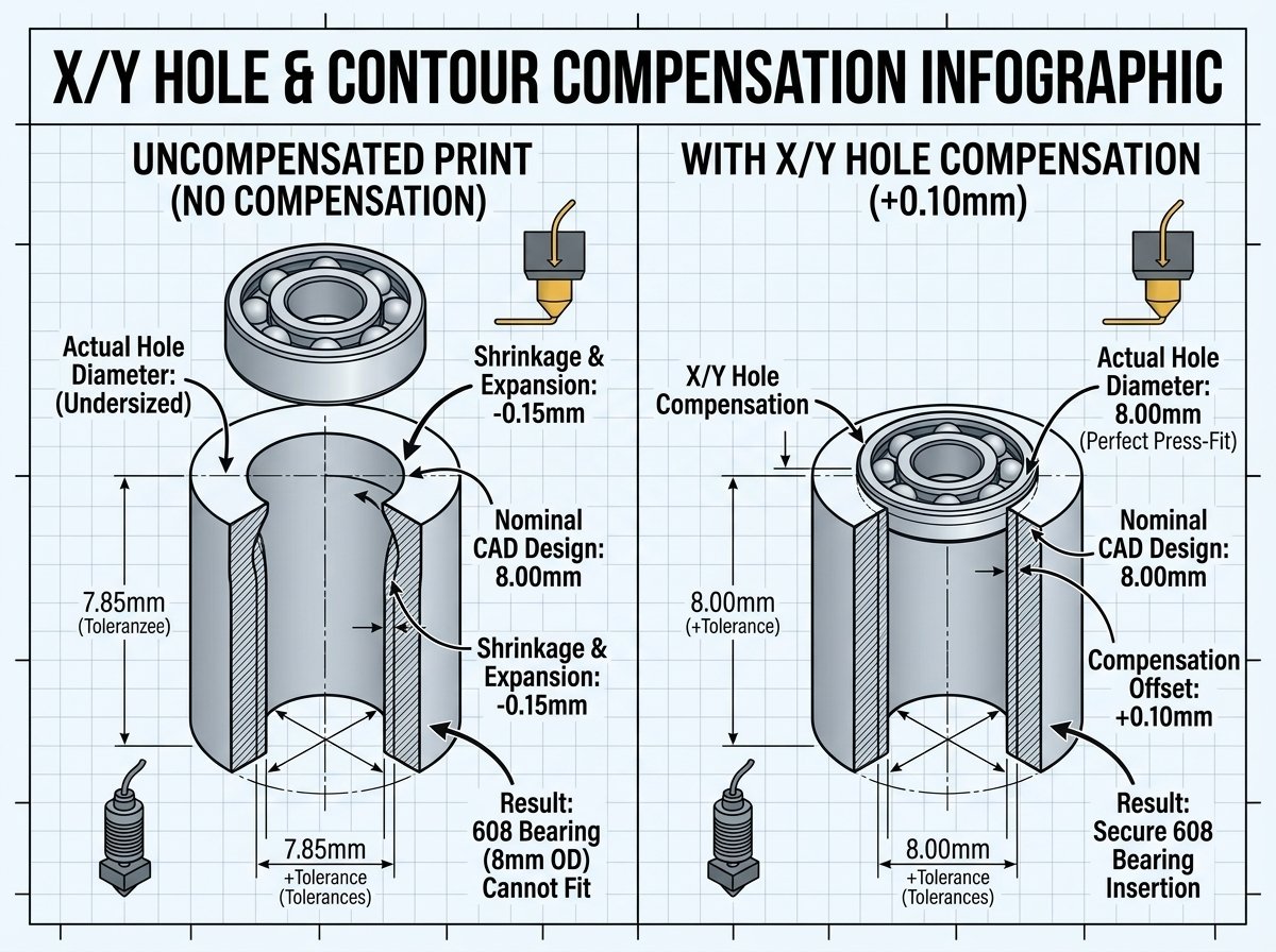
X/Y Hole Compensation offsets internal circular toolpaths outward to counter the natural inward shrinkage of cylindrical features. Setting X/Y Hole Compensation to values between +0.05mm and +0.15mm widens internal bores without altering external part dimensions, while X/Y Contour Compensation scales overall outer part boundaries.
A persistent mechanical challenge in FDM printing is that internal holes almost always print slightly smaller than designed in CAD models. This occurs due to two physical factors: polygon triangulation of circular features during STL export and hoop stress contraction as circular extrusions cool and shrink toward their center point.
Rather than continually altering original CAD geometry for every specific printer or material, you can use slicer compensation parameters to adjust physical tolerances globally:
| Slicer Parameter | Recommended Starting Value | Primary Dimensional Effect | Best Mechanical Application |
|---|---|---|---|
| X/Y Hole Compensation | +0.08 mm to +0.12 mm | Expands internal holes and bores outward without changing outer walls | Press-fit ball bearings, linear rod pass-throughs, heat-set insert holes |
| X/Y Contour Compensation | -0.03 mm to -0.07 mm | Shifts outer perimeter boundaries inward to reduce exterior part dimensions | Sliding dovetail joints, interlocking enclosure lids, pin hinges |
| Precise Outer Wall Width | Equal to Nozzle Diameter (0.40mm) | Ensures uniform bead width on exterior surfaces | Precision alignment dowels, snap-fit clips |
| Wall Generator Engine | Arachne (Variable Line Width) | Eliminates internal gap infill gaps in thin walls | Thin-walled ribs, mechanical housings, structural brackets |
When tuning X/Y compensation for functional assemblies, print a dedicated calibration block containing both internal cylindrical bores (ranging from 5mm to 22mm) and external boss pins. Measure features using a calibrated digital micrometer. If outer dimensions match CAD specs exactly but 10mm holes measure 9.85mm, set X/Y Hole Compensation to +0.07mm in your slicer profile.
How Nozzle Extrusion Width and Layer Height Impact Wall Thickness Tolerances
Ratios between extrusion line width and nozzle orifice diameter govern melt pressure stability within wall perimeters. Setting wall extrusion width to 105%–115% of nominal nozzle diameter (e.g., 0.42mm to 0.45mm on a 0.40mm nozzle) ensures consistent inter-bead squish and prevents void formation between adjacent loops.
Extrusion line geometry plays a direct role in wall rigidity and wall thickness precision:
- Thin Extrusion Lines (<100% Nozzle Width): Extruding lines narrower than nozzle orifice width (e.g., 0.35mm line on a 0.40mm nozzle) reduces internal die swell pressure. However, it increases susceptibility to flow starvation on high-speed direction changes, leading to microscopic gaps between parallel wall perimeters.
- Over-Sized Extrusion Lines (>130% Nozzle Width): While extruding wide lines (0.55mm on a 0.40mm nozzle) speeds up print times and improves layer bonding strength, high melt volume increases lateral bead bulging at layer transitions, worsening vertical surface roughness (total profile tolerance).
- Layer Height Impact on Wall Stability: Lower layer heights (e.g., 0.12mm to 0.16mm) provide a higher density of layer interfaces per millimeter of wall height. This improves vertical wall straightness compared to thick layers (0.28mm+), which exhibit more pronounced layer step-over ridges that can interfere with tight slide fits.
For engineering guidelines on geometric feature design, minimum wall thicknesses, and orientation strategies to prevent distortion, review our guide on 3D Printing Design Rules for Perfect Prints.
Z-Seam Placement and Retraction Blobs: Preventing Dimensional Bulges on Perimeter Walls
Uncontrolled Z-seam placement introduces localized wall bulges that destroy tight mechanical sliding fits. Setting Z-seam alignment to "Aligned" or "Rear" consolidates start/stop retraction points onto a single edge, while tuning Pressure Advance (K-value) flattens seam start bulges.
Every closed wall loop must start and end at a specific point on the perimeter. During this loop transition, the toolhead performs a brief pause, retraction, and un-retraction. If un-retraction flow is not perfectly calibrated, extra molten material is deposited at the seam start, creating a sharp bump that projects 0.10mm to 0.25mm past the wall surface:
- Random Seam Pitfalls: Distributing Z-seam start points randomly across perimeters scatters tiny plastic pimples all over exterior surfaces. If these bumps occur inside a cylindrical bearing bore, the bearing will bind on the seam dots rather than seating flat against the wall.
- Aligned vs. Sharpest Corner Seam Placement: Placing Z-seams on sharp external corners hides seam geometry within part angles. For round cylindrical parts where no corners exist, positioning the seam along a non-critical rear axis isolates seam bumps to an easily sandable line.
- Pressure Advance (K-Value) Integration: Calibrating Pressure Advance ensures hotend pressure drops before the toolhead reaches the loop endpoint, preventing excess plastic from oozing during nozzle travel moves. For detailed calibration procedures, consult our walkthrough on The Ultimate 3D Print Quality Test Guide.
Experimental Calibration Protocol: Measuring Wall Tolerances with Digital Micrometers
Systematic measurement of test cubes using precision micrometers reveals exact wall thickness and dimensional drift. Follow this step-by-step test protocol to calibrate wall settings before printing complex multi-part mechanical assemblies:
- Print a Single-Wall Test Cylinder: Slice a 30mm diameter hollow cylinder in Spiral Vase Mode (single perimeter wall) at a fixed 0.45mm extrusion width. Measure wall thickness at four points around the circumference using a digital micrometer. Adjust slicer Flow Ratio (Extrusion Multiplier) until measured thickness matches target 0.45mm within ±0.01mm.
- Print a Multi-Perimeter Tolerance Block: Slice a 20mm x 20mm test cube configured with 3 wall loops, Inside-Out wall order, and 15% Gyroid infill. Measure overall X and Y dimensions after the print cools fully to room temperature (20°C).
- Verify Internal Bore Fitment: Print a test plate with 5mm, 10mm, 15mm, and 22mm holes. Test-fit standard dowel pins or 608 bearings. Adjust X/Y Hole Compensation incrementally (+0.03mm steps) until press-fit items seat firmly with hand pressure without splitting layer seams.
- Document Filament-Specific Shrinkage: Different FDM polymers exhibit distinct volumetric thermal contraction rates upon cooling. While PLA shrinks minimally (~0.3%), PETG contracts moderately (~0.8%), and ABS/ASA contract significantly (1.5%–2.0%). Maintain separate X/Y compensation profiles in OrcaSlicer for each material type.
Frequently Asked Questions (FAQ)
1. What is the best wall perimeter order for 3D printed mechanical assembly parts?
For functional engineering parts requiring accurate external and internal dimensions, Inside-Out (Inner/Outer) wall order is best. Printing inner perimeters first establishes a stable foundation that prevents the final outer bead from expanding outward beyond nominal CAD boundaries.
2. How does Arachne wall generator compare to Classic wall generator for part tolerances?
The Arachne wall generator dynamically adjusts extrusion width to fill thin walls without creating vibration-heavy gap infill. It improves internal wall density and corner accuracy. However, for precise constant-width perimeters on smooth outer surfaces, calibrating Arachne's minimum feature width is recommended to avoid unnecessary line width variations.
3. Why do internal holes print undersized on FDM 3D printers?
Internal holes print small due to two factors: STL mesh triangulation (which converts smooth circles into inscribed polygons) and polymer surface tension hoop stress, which pulls circular extrusions inward toward the center as the hot plastic cools. Using X/Y Hole Compensation offsets toolpaths to correct this effect.
4. Should I change wall extrusion width when using a 0.4mm nozzle?
Yes. Setting wall extrusion width slightly wider than nozzle orifice diameter (typically 0.42mm to 0.45mm for a 0.4mm nozzle) improves layer adhesion and provides stable backpressure in the melt zone, producing consistent perimeter line geometry.
5. Can Z-seam settings cause press-fit bearings to fail?
Yes. If the Z-seam is placed randomly inside a circular bearing socket, retraction blobs will create raised bumps on the internal wall surface. These pimples prevent bearings from seating squarely. Setting seam placement to Aligned or using X/Y Hole Compensation resolves this issue.
References & External Sources
- OrcaSlicer Official Calibration & Flow Ratio Guide – Official GitHub documentation on tuning flow rates, wall perimeters, and Pressure Advance.
- Prusa Knowledge Base: Layers and Perimeters Guide – Official PrusaSlicer handbook covering External Perimeters First, Wall loops, and layer height interactions.
- Bambu Lab Wiki: Introduction to Wall Generator – Official Bambu Studio documentation detailing Arachne variable line width mode vs. Classic wall generator.
- Klipper Documentation: Pressure Advance & Tuning – Official technical guide explaining hotend pressure dynamics and corner bulging elimination.
About the Author: Dinu Suciu
Dinu Suciu is an FDM 3D printing practitioner, prototyping engineer, and founder of 3D Print Book. Operating high-speed enclosed CoreXY FDM printers, Dinu focuses on practical material testing, slicer configuration, and routine machine maintenance. Have questions about mechanical tolerances or slicer profiles? Reach out through our Contact Page.