




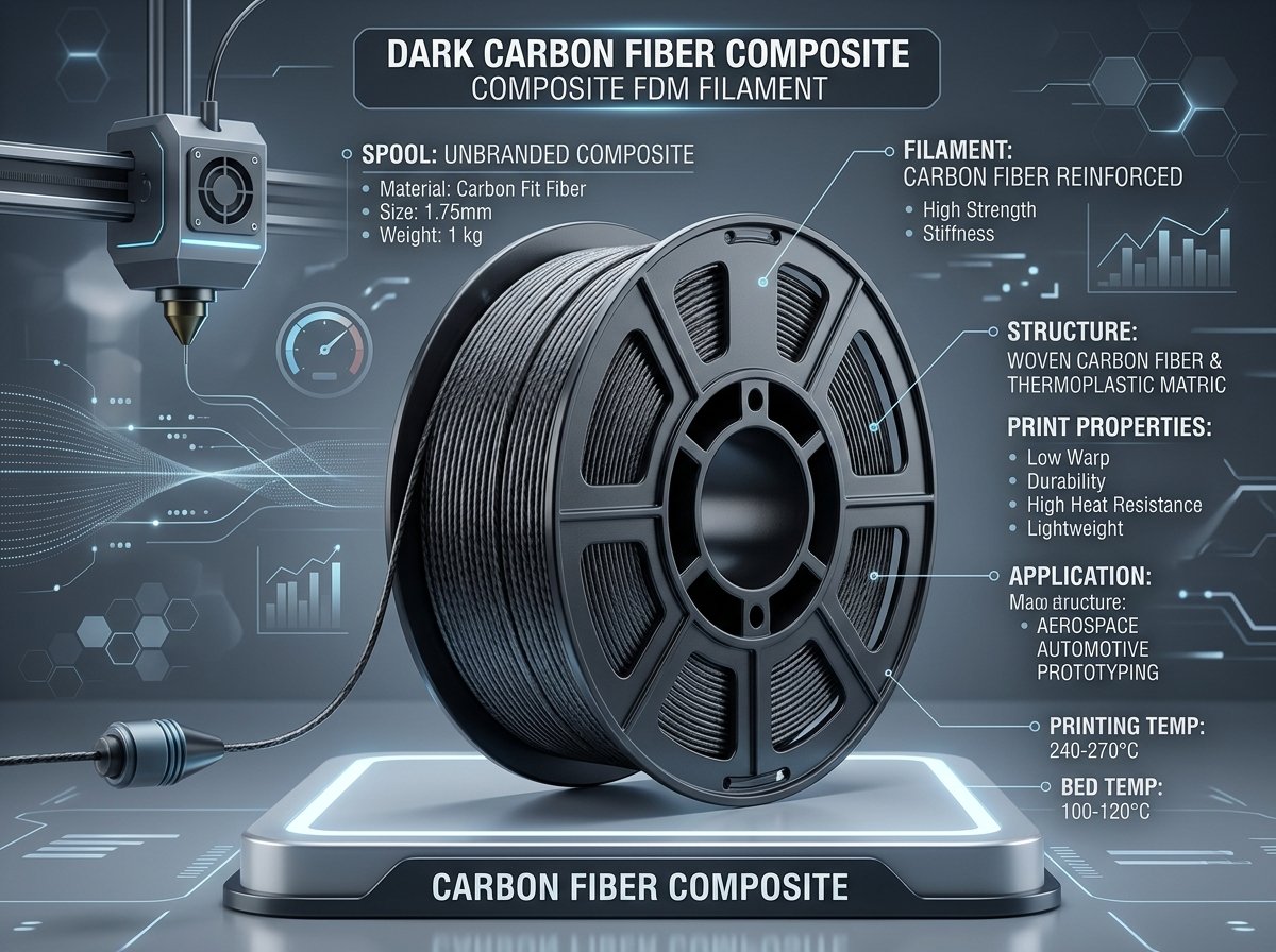
When desktop FDM 3D printing transitioned from producing rapid aesthetic prototypes to functional engineering hardware, standard neat polymers like PLA and PETG quickly exposed their mechanical boundaries. High-temperature environments, persistent bending loads, and structural vibration often caused standard thermoplastics to creep, flex excessively, or deform under load. Carbon Fiber (CF) reinforced composite filaments emerged to solve this exact problem, blending chopped carbon micro-fibers into thermoplastic base matrices.
Over the past several years operating my FDM print setup across machines like the Bambu Lab P1S, Creality K1, and Elegoo Centauri Carbon, I have printed hundreds of structural parts using composite filaments. Whether fabricating custom automotive sensor brackets, drone arm mounts, or heat-shielded enclosures, selecting the right composite matrix makes the difference between a part that lasts for years and one that fails under stress. In this guide, we will break down the mechanical physics, hardware requirements, matrix differences between PETG-CF, ABS-CF, and PA-CF (Nylon-CF), and best practices for printing composite filaments reliably.
Mechanical Performance: Carbon Fiber Reinforcement vs. Neat Polymers
Adding chopped carbon micro-fibers (typically 10% to 20% by weight) to thermoplastic polymers substantially increases tensile modulus (stiffness) and flexural rigidity while reducing volumetric thermal expansion; however, plane-directional strength and impact resistance depend heavily on the base matrix, part orientation, and layer bonding quality.
To understand why carbon fiber filaments perform so well, we must look at how the chopped micro-fibers interact with the base polymer during extrusion. Standard neat filaments consist of unreinforced polymer chains. When exposed to heat and mechanical strain, these polymer chains easily slide past one another, resulting in flex under load and noticeable thermal shrinkage during cooling.
When carbon fibers—typically microscopic strands measuring between 100 to 300 microns in length—are blended into the polymer melt, they act as internal structural rebar. As the filament passes through the nozzle orifice, shear forces align these fibers parallel to the direction of extrusion. This micro-alignment yields three primary engineering benefits:
- Significantly Higher Tensile Modulus (Stiffness): Carbon fiber composites consistently increase flexural rigidity, allowing brackets printed in PA-CF or PETG-CF to resist bending deflection under load far better than their neat counterparts.
- Drastic Reduction in Thermal Warping: Because carbon fibers possess a near-zero coefficient of thermal expansion, they mechanically restrain the polymer matrix from contracting as it cools from printing temperature to ambient room temperature. This makes large flat prints far less prone to corner lifting or warping.
- Superior Aesthetic Surface Finish: The microscopic fiber ends disrupt light reflection across print layers. Parts printed in CF composite materials feature a deep matte texture that virtually hides layer lines, creating a factory-manufactured appearance.
Important Engineering Distinction: While carbon fibers drastically increase stiffness (tensile modulus) and heat deflection temperature, they do not automatically increase Z-axis layer adhesion or impact strength. In fact, if printed at inadequate temperatures or without proper active drying, carbon fibers can slightly decrease inter-layer bonding compared to neat filaments because the non-melting fiber strands create microscopic barriers along the layer boundary.
Matrix Material Comparison: PETG-CF vs. ABS-CF vs. PA-CF
Selecting the best carbon fiber filament depends on the ambient operating temperature, mechanical load type, and printer enclosure capabilities required for your project.
It is a common misconception that all carbon fiber filaments behave similarly. The carbon fiber component provides stiffness and dimensional stability, but the base polymer matrix dictates the thermal endurance, chemical resistance, impact toughness, and printing difficulty of the final object. Let us analyze the three most prevalent composite matrices used in desktop FDM printing today:
1. PETG-CF (Polyethylene Terephthalate Glycol + Carbon Fiber)
PETG-CF is the most accessible composite filament for everyday makers and functional prototyping. Because PETG inherently resists moisture better than Nylon and does not require an enclosed print chamber, adding carbon fiber transforms PETG into an exceptionally easy-to-print structural material. It exhibits virtually zero warping, low odor, and excellent dimensional accuracy on open-frame FDM printers.
- Printing Temperature: 240°C – 260°C
- Bed Temperature: 70°C – 80°C
- Heat Deflection Temperature (HDT): ~75°C – 80°C
- Key Advantage: Prints easily without an enclosed chamber; outstanding surface finish and minimal stringing compared to neat PETG.
- Limitation: Limited heat resistance for high-temperature automotive engine bays.
2. ABS-CF / ASA-CF (Acrylonitrile Butadiene Styrene + Carbon Fiber)
ABS-CF and ASA-CF combine the lightweight, high-temperature characteristics of ABS/ASA with the rigidity of carbon fiber. Neat ABS is notoriously difficult to print on large beds due to aggressive warping and thermal shrinkage. Carbon fiber reinforcement tames ABS shrinkage significantly, allowing makers to print rigid, heat-resistant enclosures and outdoor brackets with reduced warp stress.
- Printing Temperature: 250°C – 270°C
- Bed Temperature: 90°C – 100°C (Enclosure recommended)
- Heat Deflection Temperature (HDT): ~95°C – 105°C
- Key Advantage: Moderate weight reduction, high heat resistance, easy post-processing and sanding.
- Limitation: Requires an enclosed printer chamber and active ventilation due to styrene fumes.
3. PA-CF / Nylon-CF (Polyamide + Carbon Fiber)
PA-CF represents a premier choice for heavy-duty engineering applications, functional tooling, and automotive components under the hood. Polyamide (Nylon) provides high impact toughness and solvent resistance, while carbon fiber eliminates Nylon's traditional tendency to warp severely. When properly dried, printed, and oriented to manage Z-axis layer anisotropy, PA-CF provides a high-performance, durable solution for demanding engineering components operating in continuous mechanical stress and elevated temperature environments.
- Printing Temperature: 270°C – 300°C
- Bed Temperature: 80°C – 100°C
- Heat Deflection Temperature (HDT): Up to 150°C – 190°C (requires specific high-temp formulations and thermal annealing; always verify exact values in the manufacturer's Technical Data Sheet / TDS)
- Key Advantage: Exceptional structural rigidity, chemical/oil resistance, and high thermal endurance.
- Limitation: Highly hygroscopic; requires active drying at 70°C–80°C and printing directly from a sealed dry box.
| Filament Matrix | Print Temp (°C) | Bed Temp (°C) | HDT (°C) | Enclosure Required? | Moisture Sensitivity | Best Application |
|---|---|---|---|---|---|---|
| PETG-CF | 240 - 260 | 70 - 80 | 75 - 80 | No | Low to Moderate | Rigid brackets, drone frames, jigs |
| ABS-CF / ASA-CF | 250 - 270 | 90 - 100 | 95 - 105 | Yes | Moderate | Enclosures, heat shrouds, exterior automotive |
| PA-CF (Nylon-CF) | 270 - 300 | 80 - 100 | Up to 150 - 190 (Check TDS) | Recommended | Extreme (High) | Under-hood automotive, heavy machinery tooling |
Hardened Nozzle Requirements and Extruder Gear Wear
Carbon fiber particles inside filament act like abrasive micro-files, meaning standard brass nozzles can erode rapidly and should be avoided for functional production.
One of the most critical operational errors newcomers make when trying composite materials is attempting to print carbon fiber filaments through a stock brass nozzle. Brass is a soft metal alloy. As the molten polymer carrying chopped carbon fiber fragments flows through the nozzle tip under high pressure, the microscopic fiber ends wear down the inner geometry of the orifice.
Extruding composite filaments through a standard brass nozzle causes rapid internal orifice erosion, depending on the specific fiber loading and nozzle alloy. This unpredictable wear destroys extrusion control, causes over-extrusion blobs, ruins wall tolerances, and makes regular nozzle inspection essential.
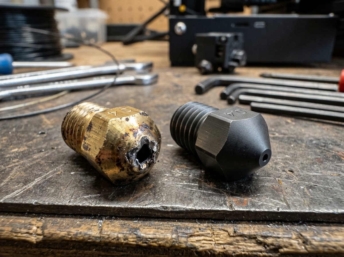
Essential Hardware Upgrades for Composite Filaments:
- Hardened Steel or Tungsten Carbide Nozzles: Swapping to an abrasion-resistant hardened steel nozzle (hardness rated above 60 HRC) or a premium tungsten carbide / ruby-tipped nozzle is strictly essential. Hardened steel resists the abrasive wear of carbon fiber completely, preserving exact orifice geometry over dozens of spools.
- Nozzle Diameter Selection (0.4mm vs. 0.6mm): While high-quality 0.4mm hardened steel nozzles handle fine-fiber composites like Bambu PA-CF or Polymaker PETG-CF well, using a 0.6mm nozzle significantly reduces the risk of nozzle clogs caused by fiber clumping. A 0.6mm orifice also speeds up print times for thick-walled functional parts.
- Extruder Gear Material Inspection: While an abrasion-resistant nozzle is strictly essential for any carbon fiber printing, inspecting your drive gear condition is equally important. Upgrading to hardened steel drive gears is a highly recommended upgrade for high-volume carbon fiber printing to prevent gradual gear tooth wear over extended production runs.
Moisture Sensitivity, Active Drying, and Annealing Composite Prints
Nylon-CF (PA-CF) absorbs atmospheric humidity within hours, requiring active drying at 70–80°C for 8 to 12 hours and direct printing from a sealed dry box to avoid steam voids and weak layer adhesion.
Moisture management is the single most decisive factor determining success or failure when working with polyamide composite filaments. Polyamide (Nylon) molecules contain amide groups that readily form hydrogen bonds with ambient water vapor. Even when blended with carbon fiber, wet PA-CF filament will boil water inside the hotend melt zone during extrusion.
When wet filament is extruded at 280°C, the trapped moisture instantly converts into high-pressure steam bubbles. This causes audible popping sounds at the nozzle tip, severe stringing, surface pitting, and up to a 50% loss in structural tensile strength due to steam voids between print layers.
Recommended Filament Drying Protocol:
- PA-CF (Nylon-CF): Dry in a dedicated filament dryer or oven at 70°C – 80°C for a minimum of 8 to 12 hours. Print directly from a desiccated active dry box during the build.
- ABS-CF / ASA-CF: Dry at 65°C – 70°C for 6 to 8 hours prior to printing.
- PETG-CF: Dry at 60°C – 65°C for 6 hours if exposed to ambient humidity for extended periods.
Post-Print Thermal Annealing for Maximum Heat Resistance
While specific high-temperature PA-CF formulations can reach Heat Deflection Temperatures (HDT) up to 150°C–190°C after thermal annealing, exact thermal limits must always be verified against the manufacturer's Technical Data Sheet (TDS). Post-print thermal annealing reorganizes polymer crystallization and improves thermal resistance, though makers must manage potential dimensional shrinkage during heating.
By placing the clean printed part in a temperature-controlled oven at 80°C to 100°C for 4 to 6 hours, polymer chains recrystallize into a dense, organized molecular matrix. Thermal annealing relieves internal molding stress, increases chemical resistance, and elevates thermal deformation limits for demanding mechanical environments.
Automotive & Functional Engineering Applications: Printing Parts That Last
Carbon fiber composite filaments like PA-CF and ABS-CF represent the best 3d printing filament for car parts due to their superior heat deflection under engine bay temperatures and structural rigidity against mechanical vibration.
In automotive engineering and custom fabrication, 3D printed components inside engine bays or passenger cabins face harsh conditions: continuous vibration, oil and fuel exposure, ambient temperatures exceeding 90°C, and structural clamping stress. Standard PLA or PETG parts installed near an engine block quickly deform or sag under load.
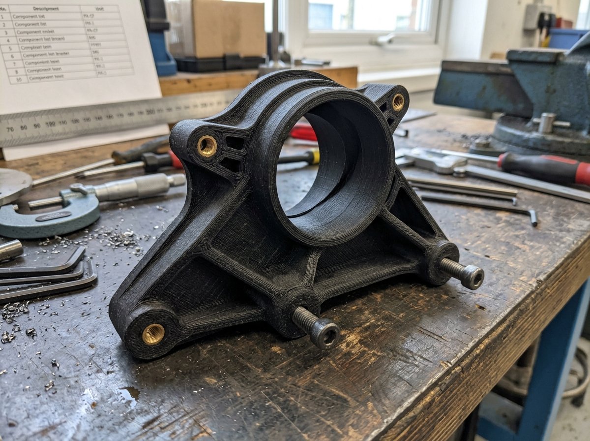
By leveraging PA-CF and ABS-CF, automotive enthusiasts and engineers can manufacture custom functional components directly on desktop FDM printers:
- Engine Bay Sensor & Hose Brackets: PA-CF handles radiant engine block heat and chemical exposure to fluids without creeping or loosening bolt torque.
- Custom Air Intake Ducts & Heat Shrouds: The high HDT of PA-CF and ABS-CF prevents structural collapse under turbocharger intake vacuum pressures and elevated air intake temperatures.
- Interior Gauge Pods & Switch Panels: ASA-CF and ABS-CF provide UV weathering resistance and a sleek matte surface finish that matches OEM dashboard trim without requiring manual painting.
- Robotic Grippers & Fixtures: High-stiffness composite parts reduce moving mass on robotic arms while maintaining high structural clamping force.
"When designing functional components for automotive or industrial machinery, always design with extra perimeter walls rather than relying solely on high infill density. Four to six solid perimeters printed with a 0.6mm hardened steel nozzle in PA-CF create a near-solid structural shell that resists crushing and bolt compression far better than a 80% infill part with thin walls."
Best Practices Checklist for Carbon Fiber FDM Printing
Before launching a long composite print job, run through this practical engineering checklist to ensure maximum success:
- Verify Hardened Nozzle Installation: Ensure your printer is equipped with a hardened steel, tungsten carbide, or ruby nozzle (0.4mm or 0.6mm). Never print CF filaments with standard brass nozzles.
- Dry Filament Thoroughly: Bake PA-CF or ABS-CF in a filament dryer at 70°C+ for 8+ hours. Keep moisture levels inside your feed box below 15% RH during printing.
- Disable or Reduce Layer Cooling Fans: Carbon fiber filaments require low cooling fan speeds (typically 0% to 20%) to allow hot polymer chains to fuse thoroughly between layers. Excess cooling leads to poor Z-axis layer adhesion.
- Clean PEI Plate with Hot Water and Soap: Ensure your build plate is free of oils. Apply a thin layer of PVA glue stick or specialized bed adhesive to act as both an adhesion promoter and a release layer for PA-CF.
- Review Wall Thickness and Orientations: Align functional load vectors parallel to the print bed so tensile forces pull along extruded fiber lines rather than against layer boundaries. Consult our comprehensive 3D printing materials guide for detailed base polymer selection.
Frequently Asked Questions (FAQ)
Q1: Can I print carbon fiber filament on a stock 3D printer without upgrades?
No. Standard stock 3D printers typically feature soft brass nozzles and stainless steel drive gears. Printing carbon fiber filaments through a brass nozzle will erode the orifice rapidly. You must upgrade to a hardened steel nozzle (or tungsten carbide) and inspect your extruder gears before printing composite materials.
Q2: Is carbon fiber filament actually stronger than regular PLA or PETG?
Carbon fiber filaments are significantly stiffer (higher flexural modulus) and far more heat-resistant than regular PLA or PETG. However, they are not necessarily stronger in Z-axis impact resistance or tensile strain at break. Carbon fiber micro-strands increase rigidity and reduce warping, but interlayer bond strength depends heavily on base matrix selection, print orientation, and dry filament.
Q3: Does carbon fiber filament emit hazardous fumes during printing?
The health impact depends on the base polymer matrix. PETG-CF emits minimal odor, whereas ABS-CF and ASA-CF release volatile organic compounds (VOCs) and styrene fumes that require an enclosed printer with HEPA/carbon filtration or room ventilation. Additionally, avoid sanding CF prints dry; always wet-sand composite parts to prevent inhaling microscopic carbon dust particles.
Q4: Why is my PA-CF print brittle or snapping between layers?
Brittle PA-CF prints are almost always caused by wet filament, inadequate extrusion temperature, or poor layer alignment relative to part loads. Ensure the filament is dried at 70°C–80°C for 10 hours, increase your hotend temperature to 280°C–290°C, and reduce your layer cooling fan speed to 0–15%.