




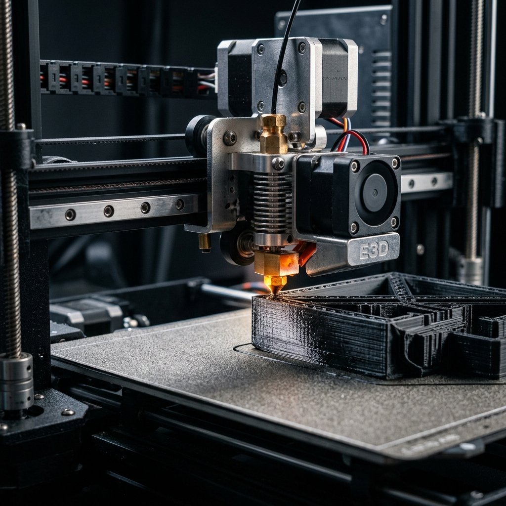
If you have ever noticed bulged, rounded corners on your 3D prints or small gaps at the start and end of extruded lines, you are dealing with the physical lag of molten plastic. While FDM 3D printers do an excellent job of positioning the printhead, managing the flow of material through the nozzle is a thermodynamic and fluid dynamic challenge. As the printhead accelerates and decelerates around corners, the pressure inside the nozzle does not change instantaneously. To solve this mechanical limitation, modern firmware utilizes a feature called Pressure Advance (in Klipper) or Linear Advance (in Marlin), scaled by a parameter known as the K-value. Learning how to calibrate Pressure Advance is one of the most critical post-calibration steps you can take to elevate the quality and structural integrity of your prints.
As the owner of 3D Print Book, I manage a variety of high-performance FDM machines. I have spent countless hours tuning extruders, modifying slicer profiles, and testing new firmware builds. In my experience, while calibrating extruder E-steps establishes a consistent volume of plastic, it does nothing to control the dynamic flow variations caused by pressure lag. In this comprehensive guide, I will take you step-by-step through the physics of nozzle pressure, explain how to identify pressure-related print defects, and provide a clear walkthrough on how to calibrate the K-value using built-in tests in OrcaSlicer and Cura.
What is Pressure Advance in FDM 3D Printing?
Pressure Advance is a firmware feature that compensates for the lag in filament extrusion pressure during acceleration and deceleration. Calibrating this value prevents under-extrusion at the start of lines and bulging at the corners.
To understand the necessity of Pressure Advance, we must visualize the hotend as a pressurized chamber. When the extruder motor pushes solid filament into the top of the hotend, it acts like a piston forcing a viscous liquid out of a tiny nozzle orifice. Because thermoplastics are elastic and have a specific viscosity when melted, they do not behave like a rigid, incompressible fluid. Instead, the filament behaves like a spring. When the extruder pushes filament down, the solid filament compresses, and the pressure inside the melt zone rises. When the extruder stops pushing, the residual pressure continues to force molten plastic out of the nozzle until the pressure is equalized.
This physical delay creates noticeable artifacts during rapid speed changes:
- Acceleration (Line Start): As the printhead moves from a standstill to its cruising speed, the extruder motor feeds filament in sync with the velocity. However, because of the elasticity of the plastic, there is a lag before the pressure inside the melt chamber reaches the required level. This results in temporary under-extrusion at the start of the line.
- Deceleration (Corner Approach): As the printhead slows down to change direction at a corner, the extruder motor slows down. However, the residual pressure built up inside the nozzle continues to push plastic out. This leads to over-extrusion at the end of the line, creating bulged, rounded corners.
Pressure Advance solves this by decoupling the extruder motor's movement from the printhead's instantaneous speed. The firmware actively predicts the pressure changes inside the nozzle. During acceleration, it pushes a small extra amount of filament (an \"advance\" of pressure) to build up the pressure instantly. During deceleration, it retracts or slows the extruder ahead of time to relieve the pressure before the nozzle reaches the corner. This feed-forward control model relies on a single calibration constant: the K-value.
The Physics of Nozzle Pressure and the K-Value
The mathematics behind Pressure Advance can be simplified into a basic linear relationship. The extra extrusion amount, \(e_{adj}\), added to the nominal extrusion feed is proportional to the rate of change of the printhead velocity, \(\frac{dv}{dt}\):
\[e_{adj} = K \cdot \frac{dv}{dt}\]Where \(K\) is the Pressure Advance coefficient (K-value), and \(\frac{dv}{dt}\) represents the acceleration of the printhead. From this equation, we can see that if the printhead is moving at a constant speed, the acceleration is zero, and the extruder behaves normally. However, during rapid changes in speed, a higher K-value will command more aggressive extruder movements to counteract the elastic lag of the filament.
Because the K-value is directly dependent on the mechanical layout of your printer and the properties of the filament, it is not a \"one-size-fits-all\" number. Two main factors dictate the scale of your K-value:
- Extruder Drive System: Direct-drive extruders have a very short path (often just a few millimeters) between the drive gear and the melting zone. This minimizes the springiness of the filament, resulting in very low K-values (typically between 0.01 and 0.08). In contrast, Bowden extruders route the filament through a long, flexible PTFE tube. The filament can flex, twist, and compress inside the tube, acting like a giant spring. Bowden systems require much higher K-values (typically between 0.30 and 0.90) to achieve the same compensation.
- Filament Elasticity and Viscosity: Harder, stiffer materials like PLA or ABS transmit force more directly and require lower K-values. Flexible materials like TPU are extremely stretchy and compress easily, requiring massive K-values to prevent severe oozing and under-extrusion. Additionally, different temperatures alter the viscosity of the molten plastic, meaning a change in temperature can affect your ideal pressure compensation. For a detailed breakdown of different FDM materials, refer to our comprehensive materials comparison guide.
\"When printing functional parts, you must shift your mindset from cosmetics to physics. A slightly glossy, hotter print with minor stringing will almost always be twice as strong as a matte, cool print that looks visually flawless but shatters along the layers at the first sign of load.\" — Dinu Suciu, Owner of 3D Print Book
Symptoms of Poorly Calibrated Pressure Advance
Before beginning the calibration process, it is helpful to identify what uncalibrated pressure looks like on physical prints. If your K-value is set to zero (disabled) or is incorrectly tuned, you will observe very specific artifacts:
1. Bulging Corners
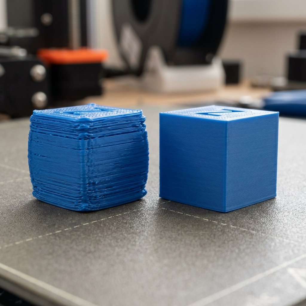
This is the most common symptom of a zero or too-low K-value. As the printer approaches a corner, it must slow down to change directions. The extruder slows its rotation, but the built-up pressure inside the nozzle continues to push plastic out. The excess plastic accumulates at the turn, creating a swollen, rounded corner. If you measure a simple 20mm calibration cube, you may find the center of the walls measures exactly 20.00mm, but the corners bulge out to 20.30mm or more. To learn more about calibrating dimensional accuracy using cubes, check out our guide on 3D print quality tests.
2. Thin Starts and Gaps
When the nozzle starts a new line after a travel move, the pressure inside the nozzle is low. As the printhead accelerates, there is a delay before the plastic starts flowing at the correct rate. This causes the first few millimeters of the line to be extremely thin, sometimes leaving gaps where the line fails to connect to the adjacent perimeter. This is a common point of mechanical failure in functional prints, as these gaps act as stress concentrators.
3. Extrusion Blobs Before Travel Moves
Just before the printhead stops printing to perform a travel move (non-printing move), the extruder stops spinning. However, the residual pressure will ooze out a small blob of plastic. This blob can catch on the nozzle during the next layer or leave unsightly zits and pimples on the surface of your prints. If you are struggling with other surface blemishes, you can reference our FDM troubleshooting guide for additional hardware checks.
Step-by-Step Guide to Calibrating the K-Value
To calibrate Pressure Advance, print a line or tower test using increments of 0.01 for direct-drive or 0.05 for Bowden extruders. Inspect the lines to find the value where corners are sharpest and line thickness is most consistent.
There are three popular methods used to calibrate the K-value: the Line Test, the Pattern/Tower Test, and the G-code generator method. We will focus on the two most user-friendly approaches: the Line Test (ideal for a quick check) and the Pattern Test (ideal for precise visual tuning).
Method 1: The Pressure Advance Line Test
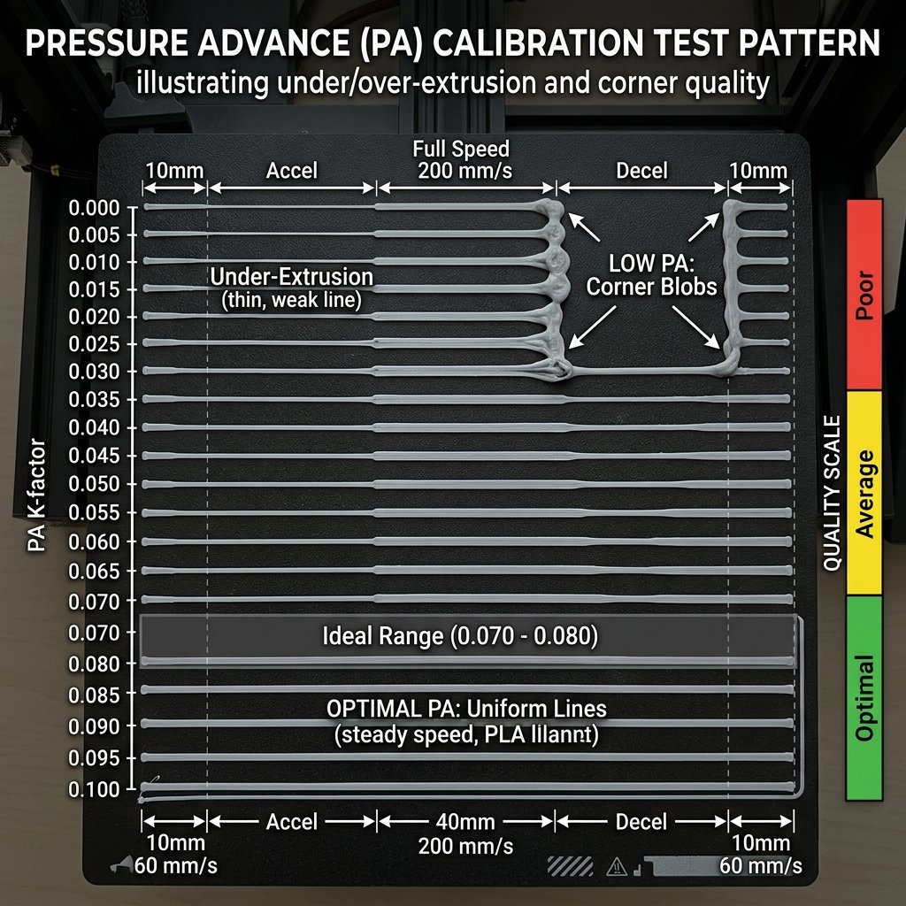
The Line Test is the fastest way to get a ballpark K-value. The printer lays down a series of straight lines on the build plate. Each line is printed at a specific K-value. The lines are split into three segments: a slow segment, a rapid acceleration to high speed, and a rapid deceleration back to slow speed. By inspecting the lines, you look for the K-value where the transition between slow and fast printing is completely seamless, with no thinning or bulging.
Follow these steps to perform the Line Test:
- Clean your build plate and ensure your first-layer bed leveling is perfect. Any adhesion issues will ruin the test.
- Open your slicer (such as OrcaSlicer) and locate the calibration menu. Select \"More Templates\" and click on \"Pressure Advance\".
- Choose the \"Line\" method. Set your starting value to 0.0, the end value to 0.1 (for direct-drive) or 1.0 (for Bowden), and the step size to 0.005 (direct-drive) or 0.05 (Bowden).
- Slice the file and print it. Ensure you are using your standard printing temperature and speed settings.
- Once printed, remove the test lines and inspect them under bright light. Look at the transition zones where the speed changes.
- Find the line that has a completely uniform thickness along its entire length. A line with a too-low K-value will have a thin middle section and fat, bulged ends. A line with a too-high K-value will have a fat middle section and thin or disconnected ends.
Method 2: The Pattern/Tower Test
If you want a highly accurate calibration that tests real-world printing geometries, the Pattern or Tower test is superior. This test slices a small, thin-walled square or a custom pattern with sharp 90-degree corners. The slicer injects code that gradually increases the K-value by a set increment for every millimeter of height. By measuring the height of the print where the corners look the sharpest and most uniform, you can calculate the exact K-value.
Here is how to analyze the physical printed tower:
- Lower Section (Low K-value): Near the bottom of the print, the K-value is close to zero. You will observe rounded, swollen corners with visible blobs.
- Middle Section (Sweet Spot): As the height increases, the corners will gradually sharpen up. The layers will look clean, flat, and perfectly aligned at the 90-degree turn.
- Upper Section (High K-value): Near the top, the K-value becomes too high. The extruder retracts too aggressively, leading to severe under-extrusion at the corners, gaps, and eventually layer splits or nozzle clogs.
Measure the height of the sweet spot using calipers, and apply the formula provided by your slicer to find the final value. For example, in Klipper, if the test increases the K-value by 0.005 per millimeter of height, and your best-looking layer is at 12mm height, your K-value is \(12 \times 0.005 = 0.06\).
How to Configure Pressure Advance in Different Slicers
Once you have determined your ideal K-value, you must input it into your firmware or slicer profile so that it is applied to all future prints. The method depends on the slicing software and firmware you run.
1. OrcaSlicer Configuration
OrcaSlicer has built-in support for managing Pressure Advance directly inside the filament profile, making it incredibly easy to manage different values for PLA, PETG, and TPU:
- Open OrcaSlicer and select your filament profile. Click on the edit (pencil) icon next to the filament name.
- Navigate to the \"Filament\" tab and look for the \"Pressure Advance\" checkbox. Enable it.
- Input your calibrated K-value into the input field.
- Set the \"Pressure Advance Mode\" to match your firmware (e.g., Klipper, Marlin, or Bambu).
- Save the profile with a descriptive name, such as \"My PLA - Calibrated PA\". OrcaSlicer will now automatically append the correct start G-code commands to apply this value whenever you slice a model with this filament.
2. Cura Configuration (Linear Advance Plug-in)
If you are using Cura with a Marlin-based printer, you can use the \"Linear Advance\" plug-in from the Ultimaker Marketplace to manage your K-value:
- Open Cura, go to the Marketplace, search for \"Linear Advance\", and install the plug-in. Restart Cura.
- Navigate to your print settings, click on the three lines to show all settings, and search for \"Linear Advance\".
- You will see a new setting called \"Linear Advance Factor K\". Input your calibrated value here.
- If you prefer to manage it in G-code, you can add the command `M900 K0.05` (replacing 0.05 with your value) to your printer's Start G-code script in the machine settings menu.
Pressure Advance Reference Guide (Typical Values)
To help you verify if your calibrated values are in the correct range, I have compiled a reference table based on typical configurations tested in our studio. Always treat these as starting guidelines, not absolute values:
| Material | Extruder Type | Bowden Length (if applicable) | Typical K-Value Range | Starting Calibration Value |
|---|---|---|---|---|
| PLA / PETG | Direct Drive | N/A | 0.015 – 0.050 | 0.020 |
| ABS / ASA | Direct Drive | N/A | 0.020 – 0.060 | 0.030 |
| TPU (Flexible) | Direct Drive | N/A | 0.080 – 0.220 | 0.100 |
| PLA / PETG | Bowden | 300mm – 400mm | 0.300 – 0.550 | 0.350 |
| PLA / PETG | Bowden | 500mm – 600mm | 0.500 – 0.850 | 0.500 |
| TPU (Flexible) | Bowden | N/A (Not Recommended) | 0.800 – 1.500+ | 1.000 |
Fine-Tuning and Troubleshooting Common Calibration Issues
Sometimes, calibrating Pressure Advance does not go as planned. Here are some common troubleshooting scenarios and how to resolve them:
The Test Lines Look Identical
If all the test lines look completely flat and rounded, or if changing the K-value seems to have zero effect on your print, your firmware may have Pressure Advance disabled or locked. In Marlin, ensure that Linear Advance is compiled in your firmware configuration (`#define LIN_ADVANCE`). In Klipper, verify that you are not overriding the value in your start macro or that your slicer is not stripping out the M900 commands. Additionally, ensure that your print speed is high enough (at least 60 mm/s) during the test; if you print too slow, there is not enough acceleration to highlight pressure differences.
Extruder Clicking or Grinding
If your extruder starts making clicking noises or grinding the filament during the calibration test, your K-value is likely set too high. A high K-value forces the extruder motor to perform extremely fast, micro-retractions and rapid pushes. If the motor or the hotend heater block cannot keep up with these rapid demands, the motor will stall and skip steps. Lower your maximum test range and try again. Ensure your nozzle temperature is hot enough to keep viscosity low, which reduces flow resistance.
Corners are Sharp but Walls Have Gaps
If you achieve perfect corners but notice that the outer walls of your prints have tiny vertical gaps or look sparse, your K-value may be slightly over-calibrated, or your slicer's retraction settings are fighting the firmware compensation. Try lowering your retraction distance slightly (by 0.2mm to 0.4mm for direct-drive) when Pressure Advance is enabled, as the firmware is already handling a portion of the pressure relief.
Frequently Asked Questions (FAQ)
Q1: What is the difference between Pressure Advance and Linear Advance?
Pressure Advance and Linear Advance refer to the exact same firmware feature, but they are named differently based on the firmware. Klipper uses the term 'Pressure Advance', whereas Marlin and RepRapFirmware call it 'Linear Advance'. Both use a K-value factor to scale the compensation.
Q2: Does Pressure Advance need to be calibrated for every single spool of filament?
Yes, to get the absolute best results, you should calibrate Pressure Advance for every material family (PLA, PETG, ABS, TPU) and brand, as different polymers have varying elasticity and viscosity. However, minor variations between different colors of the same brand can usually share the same K-value.
Q3: Why are Bowden extruder K-values so much higher than Direct Drive K-values?
Bowden extruders have a long PTFE guide tube between the drive gear and the hotend. This distance allows the filament to flex and compress inside the tube, creating significant springiness (lag) that requires a higher K-value (typically 0.3 to 0.9) to compensate. Direct Drive extruders have a very short path, resulting in lower values (typically 0.02 to 0.08).
Q4: Can Pressure Advance cause extruder motor skipping or clicking?
Yes, if your K-value is set too high, the firmware will perform aggressive retractions and rapid feed-forward pushes during acceleration. This can overwhelm the extruder motor, causing it to skip steps or click, which can lead to filament grinding.
Q5: How does print speed affect the calibrated K-value?
The K-value itself is mathematically independent of print speed because it scales dynamically with acceleration. However, printing at extremely high speeds increases the flow resistance within the hotend, which can slightly alter nozzle pressure dynamics, making a minor recalibration necessary for high-speed print profiles.
About the Author: Dinu Suciu
I am Dinu Suciu, the lead technician and owner of 3D Print Book. Operating an FDM-focused 3D printing workshop, I have spent years optimizing slicer parameters and testing the physical limits of engineering filaments. My passion lies in helping designers, engineers, and makers convert digital CAD designs into robust, functional physical prototypes that perform reliably under real-world stress. If you need assistance troubleshooting a structural component or selecting the right material properties, feel free to contact me directly via our dedicated contact page.