
Surface-glued magnets pop out after a few sharp impacts, and exposed hex nut slots invite hardware to fall out whenever a bolt comes loose. Pausing an FDM print mid-run to drop metal hardware inside a modeled cavity solves both problems cleanly, sealing steel fasteners and neodymium magnets behind solid printed walls.
In practice, embedding hardware mid-print often goes wrong on the first couple of attempts. A pocket that looks fine in CAD can end up 0.2 mm too shallow after elephant foot or slight Z-compression, causing the hot nozzle to slam straight into a magnet when the print resumes. Worse still, ferromagnetic hardened steel nozzles can pull loose neodymium magnets right out of their recesses and snap them onto the heater block.
I use pause-at-height cavities routinely in my workshop for magnetic tool trays, sensor mounts, and enclosure latches that need clean exterior faces. Whether you prefer captive embedded hardware, brass heat-set threaded inserts, or 3D printed M-threads and bolts, getting the pocket clearances, slicer pause layer, and firmware behavior right determines whether the nozzle seals the cavity cleanly or ruins a three-hour job.
Table of Contents
- Designing Internal Pockets: Radial Clearance and Z-Headroom
- Setting Layer Pauses in Orca Slicer, Bambu Studio, and PrusaSlicer
- Marlin vs. Klipper Pause Commands: M0, M25, M601, and Macros
- Hardware Embedding & Pause Command Comparison Matrix
- The Hardened Steel Nozzle Trap With Neodymium Magnets
- Bridging Over Metal Without Bed Cooling Shifts or Oozing
- Maker's Workshop Note: Testing Embedded N52 Magnets and M4 Nuts
- Frequently Asked Questions (FAQ)
- References & External Sources
Designing Internal Pockets: Radial Clearance and Z-Headroom
Internal cavities for embedded hardware need roughly 0.20 mm of radial perimeter clearance and 0.25 to 0.40 mm of extra vertical Z-headroom so the inserted part sits completely below the active nozzle plane.
Many makers measure an 8 × 3 mm disc magnet with calipers, draw an 8.0 mm cylinder that is 3.0 mm tall in CAD, and hit print. Real-world FDM extrusion almost never leaves a cavity that exact. Inner circular walls shrink slightly inward as molten polymer cools, and the first bridging layer over the top edge can droop slightly if there is no headroom.
On top of plastic shrinkage, cheap commercial magnets and stamped steel hex nuts vary more than most datasheets imply. An M4 DIN 934 nut typically measures around 7.0 mm across the flats, yet zinc plating and stamped burrs frequently push real parts to 7.15 mm. Nominal 3.0 mm thick neodymium magnets routinely measure anywhere from 2.80 mm to 3.05 mm depending on the batch and nickel plating thickness.
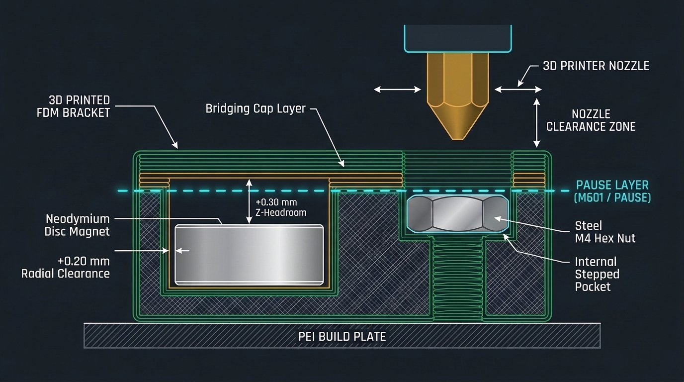
Figure 1: Pocket geometry cross-section illustrating radial fit margin, mandatory vertical Z-headroom, and where the capping bridge layer clears the inserted hardware.
Before you export your STL or STEP file, build these practical dimensional margins into your pockets:
- Radial Clearance (XY Plane): Add +0.15 mm to +0.25 mm to the measured diameter of circular magnets, or +0.20 mm to +0.30 mm across the flats of a hex nut. You want the hardware to seat firmly with light thumb pressure rather than needing a hammer—forcing a nut into an undersized slot near the edge can crack layer bonds or pop the print off the plate.
- Vertical Headroom (Z Axis): Add at least one full layer height—typically +0.20 mm to +0.40 mm—above the actual measured thickness of your magnet or nut. Because slicers round cavity depth to discrete layer steps (0.16 mm or 0.20 mm increments), always round up to the next layer boundary rather than down.
- Chamfered Pocket Bottoms or Stepped Floors: If the cavity sits near the build plate where elephant foot can tighten the first layers, add a small 0.40 mm chamfer or keep at least 3–4 bottom solid layers beneath the pocket floor.
- Negative Part Modifiers in the Slicer: When working with an existing STL model that lacks pockets, right-click the model in Orca Slicer or Bambu Studio, choose Add Negative Part, drop in a cylinder or prism, scale it to your hardware plus clearance, and place it inside the shell before slicing.
Keep in mind a simple rule for thin magnets near outer walls: leave at least two solid perimeter layers (around 0.80 mm to 1.00 mm) between the magnet face and the exterior surface you want it to grip through. Every extra millimeter of plastic between a neodymium magnet and a steel surface reduces pull force sharply, so keeping the capping shell at three top layers (0.60 mm at 0.20 mm layer height) gives strong magnetic coupling while still bridging cleanly.
Setting Layer Pauses in Orca Slicer, Bambu Studio, and PrusaSlicer
To seal a pocket cleanly, scrub the slicer's layer preview slider to the very first layer that bridges across the cavity roof and insert the pause at the start of that capping layer.
This single detail catches even experienced users off guard. In Orca Slicer, Bambu Studio, and PrusaSlicer, adding a pause at Layer N tells the printer to stop before printing Layer N—meaning right at the beginning of that layer's toolpath, after Layer N-1 has finished.
If your cavity stops opening at Layer 24 and Layer 25 is the first solid bridge covering the pocket, placing the pause on Layer 24 stops the printer one layer too early, before the top walls of the pocket are finished. Placing the pause on Layer 25 lets the printer finish Layer 24 completely, park the toolhead safely, and wait for you to insert the hardware before Layer 25 seals the roof.
Here is the quick workflow I follow across modern slicers:
- Slice the Part First: Configure your wall loops, infill, and layer height (for example, 0.20 mm standard profile) and click Slice Plate. Never place pause markers before finalizing layer height, because changing from 0.20 mm to 0.16 mm shifts every layer index.
- Inspect the Cavity in Preview Mode: Use the vertical layer slider on the right edge of the Preview screen to step upward layer by layer. Watch the top of your magnet or nut cavity closely.
- Find the First Bridging Layer: Stop on the exact layer where you first see infill or bridge lines spanning straight across the open pocket. Verify with the horizontal travel slider that the previous layer (N-1) left the pocket walls completely open and finished.
- Insert the Pause Command: Right-click the plus (+) icon on the layer slider handle. In Orca Slicer and Bambu Studio, select Add Pause. In PrusaSlicer, select Insert pause print (M601) and optionally enter a short LCD prompt such as "Drop magnets and check polarity".
- Re-Slice and Confirm the Marker: Re-slice if prompted, then scroll the preview back to that layer to confirm the pause marker sits at the start of the capping layer, not mid-pocket.
Also watch out for Print Sequence: By Object (sequential printing). As documented in the Prusa Knowledge Base, layer pause markers don't apply reliably when printing multiple objects sequentially one after another because layer numbers no longer share a single global Z-order across the plate. Switch back to By Layer whenever you embed hardware across multiple parts on one build plate.
Marlin vs. Klipper Pause Commands: M0, M25, M601, and Macros
Different FDM firmwares interpret pause G-code differently: Prusa printers use M601, standard Marlin machines often rely on M0 or M25 depending on display support, and Klipper requires the [pause_resume] module paired with a configured PAUSE macro.
If you slice in PrusaSlicer or Orca Slicer for a custom bed-slinger or an enclosed CoreXY machine running Klipper, choosing the wrong pause command in your printer profile can cause the machine to blow straight past the pause without stopping—or halt with an unrecognized G-code warning.
- PrusaSlicer / Bambu Studio Native Profiles: Stock Prusa firmware responds directly to
M601, parking the extruder cleanly and holding bed and nozzle temperatures (with a timeout warning if left idle too long). Bambu Lab machines handle Orca and Bambu Studio'sAdd Pausenatively viaM400 U1, parking over the purge chute and prompting on the printer screen and mobile app. - Marlin Firmware (M0, M1, M25, M600): Classic Marlin boards vary depending on what the manufacturer enabled when compiling firmware. Standard
M0triggers an unconditional stop waiting for an LCD button press, though some touchscreen-only Ender or Neptune boards ignoreM0when the screen runs separate serial firmware. On SD-card-only Marlin builds,M25pauses SD reading, whileM600invokes filament change—which works for pausing, though it unnecessarily unloads and purges filament unless you only want a short toolhead park. - Klipper Firmware (Mainsail / Fluidd / Creality K1): Klipper does not enable Marlin's
M0orM601out of the box unless yourprinter.cfgincludes[pause_resume]and maps those codes toPAUSE. In Orca Slicer, go to Printer Settings > Machine G-code > Pause G-code and check whether it emitsPAUSEorM601. Adding simple[gcode_macro M601]and[gcode_macro M0]wrappers that callPAUSEinsideprinter.cfgprevents unexpected missed pauses regardless of which slicer profile you load.
Workshop Rule: Never trust an unverified pause command on a six-hour functional print. Run a 5-minute 20 × 20 × 6 mm calibration block with a pause at 3.0 mm first to verify that your printer actually parks, keeps its stepper motors energized, holds bed temperature, and resumes smoothly at the exact XY coordinate.
Hardware Embedding & Pause Command Comparison Matrix
The following technical comparison outlines how different firmware pause mechanisms, hardware pocket types, and nozzle alloys behave during mid-print hardware embedding on FDM printers:
| Configuration / Method | Target Hardware & Clearance | Pause Trigger / Behavior | Primary Risk Factor | Workshop Mitigation |
|---|---|---|---|---|
| Bambu Studio / Orca Native Pause | Neodymium discs & M3–M6 hex nuts (+0.20 mm XY, +0.30 mm Z) | M400 U1 parks toolhead over chute; holds bed temp; resumes via screen or app |
Magnetic pull from stock hardened steel or stainless nozzles | Anchor magnets with thick CA glue gel or switch to non-magnetic brass/carbide |
| PrusaSlicer M601 Pause | Embedded nuts, magnets, bearings, steel dowel pins | M601 parks head off print; displays custom LCD prompt; waits for user click |
Disabled when sequential ("By Object") printing is active | Keep "By Layer" mode enabled; verify N is the first bridging layer |
| Klipper PAUSE Macro | Any captive hardware in Voron, Creality K1, or Klipperized bed-slingers | Executes PAUSE macro via [pause_resume]; parks at safe corner Z-lift |
Idle timeout (often 600s default) disables steppers and heated bed | Keep swaps under 3–5 minutes or temporarily bump idle_timeout to 1800s |
| Marlin M0 / M25 / M600 | Standard PLA/PETG brackets with captive hex nuts or washers | M0 (LCD pause) or M25 (SD pause); M600 triggers full filament unload |
Touchscreen Marlin boards sometimes ignore M0 silently |
Test a 5-minute cube; switch to M25 or custom M600 if M0 fails |
| Captive Hex Nut Pocket (Hex Recess) | DIN 934 M3/M4/M5 nuts (+0.25 mm across flats, +0.30 mm vertical gap) | Non-magnetic stainless (A2/304) vs zinc-plated carbon steel nuts | Bolt tip bottoming out or pushing nut upward if pocket is too shallow | Model an internal bolt clearance bore below the nut so screw tips pass freely |
| Neodymium Magnet Pocket (Disc/Block) | N35–N52 magnets (+0.20 mm diameter, +0.30 mm height, 0.6–0.8 mm wall skin) | Polarity reversal or nozzle attraction lifting magnet above pause layer | Magnet flipping upside down or jumping onto a steel nozzle tip | Mark north/south poles with a Sharpie stack jig; seat with CA glue + activator |
Workshop Sourcing & Non-Magnetic Nozzle Upgrades
Embedding neodymium magnets reliably starts with accurate digital calipers for measuring real nut and magnet tolerances, dependable PETG or PLA+ spools that bridge cleanly over metal, and non-magnetic brass or tungsten carbide nozzles that won't yank loose magnets out of their pockets. Before paying full retail for replacement hotends, spare nozzles, or engineering filament multipacks, check our verified 3D Printing Deals & Coupons page for active manufacturer discounts and bundle offers from brands like Elegoo, Creality, Anycubic, and Flashforge.
The Hardened Steel Nozzle Trap With Neodymium Magnets
Hardened steel nozzles and steel heater blocks are strongly ferromagnetic, meaning they can pull unglued neodymium magnets straight out of an open cavity as the toolhead passes overhead on the first bridging layer.
This is easily the most common mid-print surprise when makers move from older brass-nozzle bed-slingers to modern enclosed CoreXY machines. Printers shipped with hardened steel nozzles or steel hotend assemblies—standard on machines upgraded for carbon fiber filaments and common across newer quick-swap toolheads—have plenty of iron right at the tip. When an 8 × 3 mm or 10 × 3 mm N52 magnet sits loosely inside a dry pocket with +0.20 mm clearance, the passing steel nozzle creates enough magnetic attraction at 0.20 mm Z-distance to flip the magnet upright or yank it completely out of the print.
Once a magnet clamps onto a 220°C nozzle tip or jams sideways in the pocket, the next perimeter pass slams into it, skips steps, or shears the print right off the textured PEI plate. Note that nozzle alloy selection plays a direct mechanical role here; if you want to compare thermal behavior and alloy properties across brass, hardened steel, and tungsten carbide nozzles, alloy magnetism is another practical factor worth keeping in mind.
Three straightforward habits eliminate this failure mode:
- Anchor Every Magnet With Thick CA Gel: During the pause, place one small drop of medium or gel cyanoacrylate (superglue) into the bottom center of the pocket before pressing the magnet down. Gel CA stays put instead of wicking up the magnet walls, and touching the edge lightly with non-magnetic brass or plastic tweezers holds it flat for five seconds until it grabs. Avoid spraying liquid CA activator aggressively inside an enclosed printer chamber—excess mist can fog polycarbonate doors or leave white residue on rails.
- Use Brass or Non-Magnetic Tungsten Carbide Nozzles for Magnet Jobs: Standard C360 brass is completely non-magnetic, and pure tungsten carbide with a non-magnetic nickel-cobalt binder (depending on the manufacturer's binder alloy) generally shows dramatically lower magnetic pull than tool steel. Still, even with a brass nozzle, remember that linear rails, steel fan screws, or steel thermistor clips inside the toolhead sit only a few millimeters higher, so gluing strong N52 magnets in place remains good practice.
- Always Check Polarity With a Reference Stack: Mixing up north and south poles inside a sealed enclosure is permanent—you cannot pry a buried magnet out without destroying the part. Keep a stack of magnets wrapped in painter's tape with a bold black Sharpie dot marking the upward-facing pole, or stick one master magnet to your tweezers handle and verify that every magnet slides off in the same orientation before pressing it into the pocket.
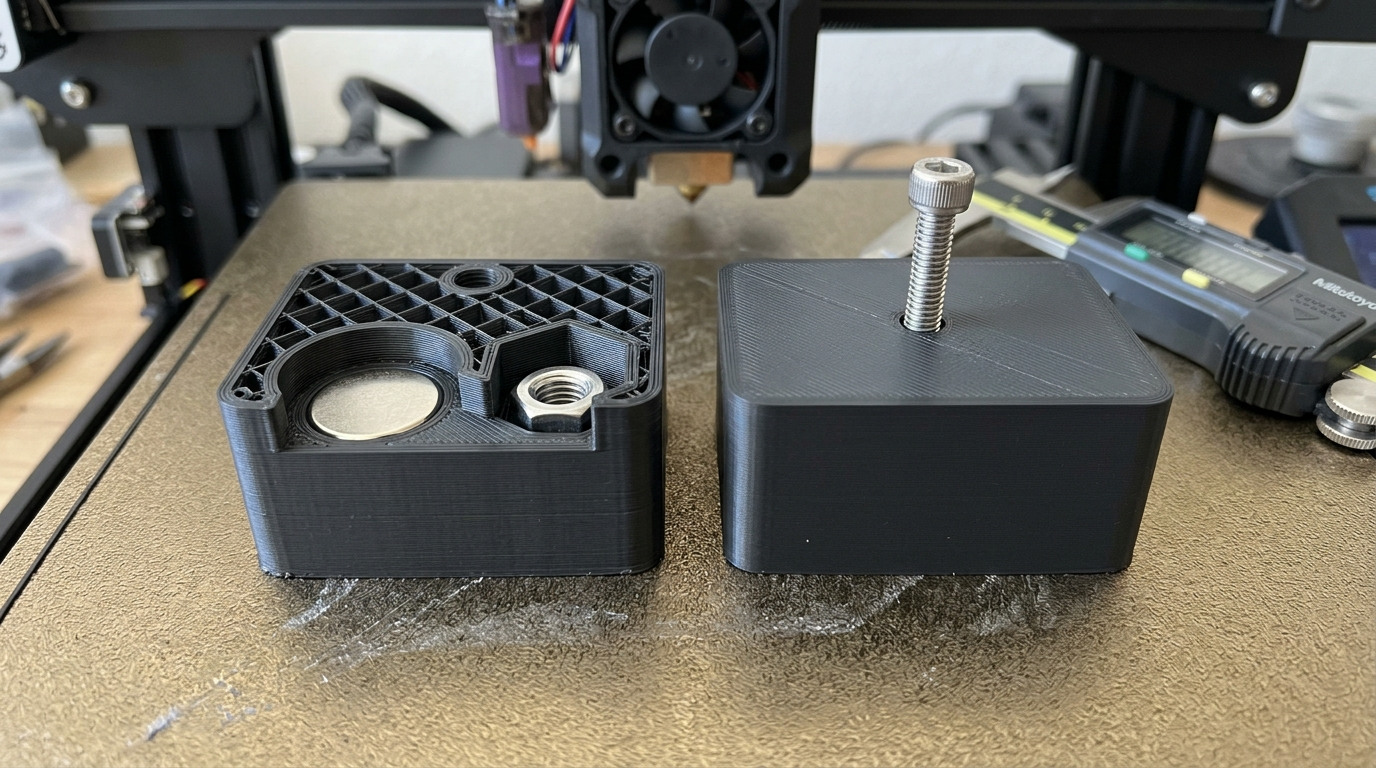
Figure 2: Workshop specimens on a textured PEI sheet showing clean seated hardware below the pause rim (left) and a fully sealed bracket with zero top-surface scarring or nozzle collision (right).
Bridging Over Metal Without Bed Cooling Shifts or Oozing
Keep the heated bed powered on throughout the pause, wipe any oozed filament tail off the nozzle tip right before resuming, and run normal bridging fan speeds so the capping layer spans cleanly over the metal insert without pulling the print off the plate.
When a print sits paused for ten minutes while you answer a message or search for the right hex nut, two subtle issues can derail the resume pass: thermal bed contraction and stepper timeout.
First, watch your firmware's idle timeout. Klipper and many Marlin builds automatically shut off the heated bed and disable stepper motors after 10 minutes (600 seconds) of inactivity as a safety feature. If the PEI bed cools from 60°C down to room temperature, a large PLA print can release partially from the plate before printing resumes—and if the Z or XY steppers turn off, gravity or your hand pressing a tight nut into the pocket can nudge the gantry out of alignment by a fraction of a millimeter, leaving an ugly horizontal layer shift right at the pause height.
To prevent bed release and toolhead ooze when resuming:
- Stage Hardware Before Starting the Print: Lay out your exact count of nuts or magnets, non-magnetic tweezers, and superglue gel on your desk before you hit Print. Keeping the pause window under 60–90 seconds avoids idle timeouts and keeps bed temperature completely steady.
- Don't Lean Heavy Force on the Build Plate: Size pockets so nuts and magnets drop in smoothly with light fingertip or tweezers pressure. Pushing hard downward against cantilevered beds (common on bed-slingers or leadscrew-cantilevered CoreXY frames) can deflect the bed springs or skip a Z-axis step.
- Clear Nozzle Ooze and Use a Purge Line or Infill Lead-In: While parked, PETG and wet PLA tend to ooze a thin 10 mm string from the hot nozzle. Snip or wipe that string off with brass tweezers or a folded paper towel just before pressing Resume. In Orca Slicer, enabling Infill Before Walls on or right after the pause—or verifying that the slicer primes into internal infill first—prevents a brief under-extrusion void on the outer wall right after resuming.
- Manage Cooling Over Metal Surfaces: Metal magnets and steel nuts conduct heat rapidly. If you coat the top of a magnet with thin glue or leave grease from bare fingers on a hex nut, the first bridging strand won't stick to the metal—which is actually fine because bridges anchor to the surrounding plastic perimeter walls, not the insert itself. Let your slicer run normal 80–100% part cooling on that bridging pass so the plastic spans taut across the pocket without sagging onto the metal face.
Maker's Workshop Note: Testing Embedded N52 Magnets and M4 Nuts
Maker's Workshop Note: Testing Embedded N52 Magnets and M4 Nuts
In my workshop tests on my Bambu Lab P1S (fitted with a hardened steel 0.4 mm nozzle) and my Creality K1C (running Klipper with a brass 0.4 mm nozzle), I ran a series of functional enclosure latch blocks using Polymaker PolyLite PLA (215°C hotend, 60°C textured PEI bed, 0.20 mm layer height) and eSUN PETG (245°C hotend, 75°C bed) to compare pocket tolerances and nozzle behavior.
Test 1: Clearance Fit on DIN 934 M4 Hex Nuts and 8 × 3 mm N52 Magnets
My M4 stainless hex nuts measured 6.96 mm across the flats and 3.12 mm tall, while my 8 × 3 mm N52 discs measured 7.98 mm in diameter and 2.86 mm thick. When I modeled exact 7.00 mm hex slots and 8.00 mm circular pockets with 3.00 mm depth, the M4 nuts refused to drop in without pressing hard enough to flex the bed, and one magnet sat nearly flush with the 3.00 mm top rim. Opening the radial CAD clearance to +0.20 mm (7.20 mm across flats, 8.20 mm diameter) and increasing pocket depth to 3.40 mm (17 layers at 0.20 mm, pausing at layer 18) allowed both inserts to drop cleanly inside with roughly 0.30 mm–0.50 mm of vertical headroom. Every capping bridge printed flat across the top without a single nozzle scrape.
Test 2: Hardened Steel Nozzle Pull vs. Brass Nozzle With Unglued Magnets
To confirm how aggressive magnetic pull really is on a steel hotend, I dropped two dry, unglued 8 × 3 mm N52 magnets into test pockets on the Bambu Lab P1S (hardened steel nozzle) and the Creality K1C (brass nozzle). On the P1S, the moment the toolhead moved across the pocket to begin the bridging cap, the steel nozzle yanked both dry magnets straight upward out of their 3.40 mm pockets and snapped them onto the heater sock before finishing the first perimeter. Repeating the identical test on the P1S with a single pinhead drop of thick CA gel under each magnet kept both magnets locked flush while the hardened steel nozzle bridged cleanly overhead. On the Creality K1C with a brass nozzle, dry magnets stayed seated—though I still prefer gluing strong N52 discs anyway so vibration at 300 mm/s travel speeds can't rattle them.
Test 3: Captive Nut Bolt-Pass Clearance
On an earlier PETG motor mount bracket, I forgot to model an extra 4 mm hole deeper below the captive M4 hex nut cavity. When I threaded an M4 × 16 mm socket cap screw through the bracket, the bolt tip bottomed out against the solid floor beneath the nut and acted like a jackscrew, pushing upward and delaminating the three top layers right above the captive nut. Adding a dedicated 4.5 mm through-clearance pocket beneath the nut seat fixed the issue completely on the next print, letting the bolt tighten down against the outer flange while pulling the nut securely against the underside of the reinforced internal plastic ceiling.
Frequently Asked Questions (FAQ)
1. What is the safest clearance to add for embedded magnets and hex nuts?
Start with +0.20 mm across the diameter or hex flats (0.10 mm per wall side) and +0.25 to +0.40 mm of extra vertical Z-height above the hardware's actual caliper-measured thickness. Because printers differ slightly in extrusion flow and pressure advance, printing a quick 10-minute pocket test strip with +0.15, +0.20, and +0.25 mm slots is worth testing before running a large multi-hour enclosure.
2. Should I put the pause on the last open layer of the pocket or the first covering layer?
In Orca Slicer, Bambu Studio, and PrusaSlicer, put the pause on the first solid/bridging layer that covers the pocket. Slicer layer pauses execute at the start of the selected layer before any extrusion on that layer begins, ensuring the pocket walls beneath are 100% finished and open for your hardware.
3. Will molten plastic stick to a magnet or nut when bridging over it?
Hot PLA or PETG rarely bonds strongly to smooth nickel-plated magnets or zinc-plated steel nuts, especially because the metal conducts heat away quickly. That isn't a problem—the capping layer anchors to the surrounding printed perimeter walls on all sides, trapping the hardware mechanically inside the solid shell.
4. How can I add a magnet cavity to an STL file I downloaded without using CAD?
Both Orca Slicer and Bambu Studio let you carve pockets directly on the build plate. Right-click your STL object, select Add Negative Part, pick a Cylinder (for round magnets) or Cube/Custom STL, scale it to your hardware dimensions plus +0.20 mm clearance, move it into position inside the model, slice, and add your pause on the covering layer.
5. Why did my Klipper printer ignore the pause I added in PrusaSlicer or Orca Slicer?
Some Klipper configurations lack a macro alias for Marlin's M601 or M0 command. Check your slicer's Pause G-code setting under Printer Settings: set it to PAUSE for Klipper machines, or add [gcode_macro M601] calling PAUSE inside your printer.cfg alongside the required [pause_resume] section.
Related Guides & Next Steps
3D Printed Threads: Model Strong M-Threads and Bolts
Master CAD design rules and slicer tolerances for 3D printed threads and bolts. Learn pitch limits, 45-degree flank profiles, XY offsets, and print orientations.

3D Printing Design Rules: DfAM Tips for Perfect Prints
Learn essential design rules like wall thickness, tolerances for moving parts, overhang mitigation, and support orientation to design better parts.
References & External Sources
- Prusa Knowledge Base: Insert Pause or Custom G-code at Layer (M601)
- Klipper Official Documentation: G-Codes Reference & PAUSE / RESUME Commands
- Marlin Firmware Documentation: M0–M1 Unconditional Stop Command
- Marlin Firmware Documentation: M25 Pause SD Print Reference
About the Author: Dinu Suciu
I am Dinu Suciu, founder and prototyping specialist at 3D Print Book. Operating an active maker workshop equipped exclusively with desktop FDM 3D printers—including enclosed CoreXY machines and direct-drive bed-slingers—I focus on mechanical tolerances, slicer calibration, and practical workshop workflows that hold up under real-world use. Have a project question or need custom functional prints? Reach out directly through our Contact Page.