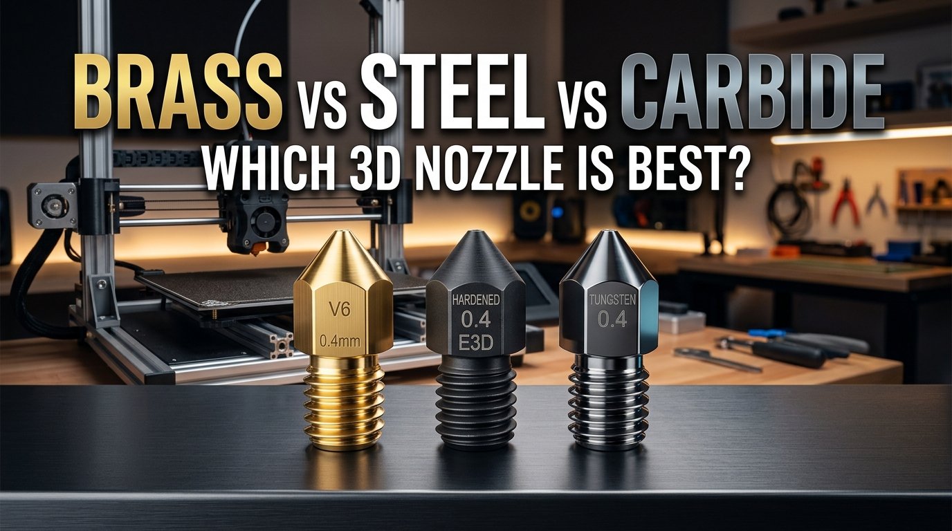
The rapid rise of high-speed CoreXY machines and fiber-reinforced filaments has turned hotend nozzle selection from a simple maintenance afterthought into a core thermal engineering decision. When makers push beyond standard PLA into carbon-fiber nylon, glass-filled PETG, or ceramic phosphorescent blends, the standard yellow brass nozzle installed at the factory faces immediate physical destruction.
In community printing hubs like r/3Dprinting and r/FixMyPrint, one recurring hardware mystery catches hundreds of makers off guard every week. A user loads an abrasive filament into a stock brass nozzle and watches print quality degrade mid-spool as the 0.40mm orifice balloons into an uneven 0.80mm crater. Yet when they swap to a hardened steel nozzle to stop the abrasion, their high-speed prints suddenly suffer from chronic matte banding, rough layer lines, and severe cold-core under-extrusion. That drop in print quality stems from a sharp thermal bottleneck: hardened tool steel transfers heat at less than a quarter of the rate of brass.
Finding the right nozzle for your toolhead requires balancing thermal conductivity against abrasive wear resistance. In this technical guide, we examine the metallurgical trade-offs between standard free-machining brass, heat-treated hardened steel, and solid tungsten carbide. We analyze real thermal transfer rates, outline the exact slicer offsets and hotend PID auto-tune steps required for steel, and explain why tungsten carbide has emerged as the premier one-nozzle solution for modern high-speed additive manufacturing.
Table of Contents
- Thermal Conductivity vs Abrasive Wear: The Material Trade-Off
- How Abrasive Fillers Destroy Brass: Carbon, Glass, and Glow Powders
- Comprehensive Benchmark Matrix: Brass vs Steel vs Carbide
- Tuning for Hardened Steel: Temperature Offsets and PID Calibration
- Volumetric Flow Throttling: Compensating for Low Thermal Conductivity
- Tungsten Carbide: The Ultimate All-Rounder Upgrade
- Evaluating Other Options: Plated Copper, CHT, and Ruby Nozzles
- Maker's Workshop Notes: Dinu's Real Lessons from the Workbench
- Frequently Asked Questions (FAQ)
- References & External Sources
Thermal Conductivity vs Abrasive Wear: The Material Trade-Off
Brass transfers thermal energy into polymer melt zones rapidly with a conductivity of roughly 115 to 125 W/m·K, while hardened tool steel provides superior wear resistance at the cost of a sluggish 20 to 30 W/m·K thermal transfer rate. Choosing a nozzle material requires managing this trade-off between melt capacity at high volumetric speeds and mechanical resistance against abrasive filament fibers.
To understand why this metallurgical difference matters, consider how an FDM hotend transfers heat. Thermoplastic filament enters the heatblock as a solid 1.75mm cold cylinder at room temperature. In modern high-speed printers moving between 200 mm/s and 400 mm/s, that cold polymer spends less than 150 milliseconds traveling through the heated internal chamber before passing out through the tip. During that fraction of a second, heat must conduct through the outer nozzle wall and penetrate all the way into the center of the filament strand.
The Thermal Bottleneck Inside Hardened Steel
Because brass (typically alloy CW614N / CuZn39Pb3) is rich in copper, heat conducts from the heater block cartridge through the nozzle body with minimal thermal resistance. The inside surface of the nozzle tip stays within 1°C to 2°C of the thermistor reading. When polymer rushes through, the brass body transfers replacement thermal energy into the melt pool almost immediately.
Hardened steel (often heat-treated SKD11, A2, or 440C tool steel) presents a drastically higher thermal resistance. With thermal conductivity hovering around 25 W/m·K, heat struggles to travel from the outer threaded body to the inner melt channel. As filament feed rates climb, the passing plastic draws heat away faster than the steel can replenish it from the heater block. While the printer's thermistor reports a stable 220°C at the aluminum heater block, the actual polymer exiting the steel tip may drop as low as 195°C. This internal temperature deficit creates severe sub-surface viscosity increases, causing clicking extruder gears, weak layer lamination, and dull, rough exterior walls.
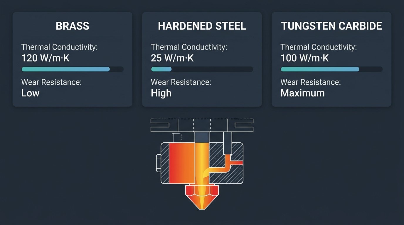
Figure 1: Thermal conductivity curves and abrasive wear hardness comparison across common 3D printing nozzle alloys.
Material Hardness and Wear Ratings
While brass excels at transferring heat, its copper-zinc matrix is soft. Standard machining brass registers between 130 and 160 on the Vickers hardness scale (HV), roughly equal to a 3 on the Mohs mineral scale. This makes brass easy and inexpensive to cut with micro-drills during manufacturing, but leaves the internal bore completely unprotected against hard filler particles.
Hardened tool steel undergoes specialized quenching and tempering processes that raise its surface hardness to 550–700 HV (55–62 HRC, or roughly 7.5 on the Mohs scale). This elevated surface hardness allows the nozzle to withstand hundreds of hours of contact with abrasive fibers without measurable dimensional drift at the orifice exit.
How Abrasive Fillers Destroy Brass: Carbon, Glass, and Glow Powders
Abrasive filaments ruin brass nozzles by dragging microscopic, razor-sharp mineral or ceramic particles across the soft internal taper under high pressure, widening the exit hole and flattening the nozzle face. Understanding the exact abrasive additives in your filament allows you to switch nozzle materials before ruining your print calibration.
Many makers assume that filament abrasiveness is limited to high-end industrial engineering plastics. In reality, some of the most destructive filaments on the market are sold as everyday aesthetic materials. When evaluating the best 3d printing filament for structural or visual projects, you must check the Mohs hardness of the internal additives:
- Carbon Fiber (CF) Blends: Filaments like PETG-CF, PLA-CF, and PA-CF contain short chopped carbon fibers measuring 5 to 10 micrometers in diameter. While carbon feels light, these chopped fiber needles register a 6 to 7 on the Mohs hardness scale. Under 3 to 5 bars of extrusion pressure, these fibers act like miniature broaching chisels, gouging the brass orifice from a clean 0.40mm circle into a jagged 0.65mm or 0.80mm funnel within a single 500-gram spool.
- Glass Fiber (GF) Reinforcements: Filaments like PA6-GF or PP-GF use milled borosilicate or E-glass fibers. Glass ranks at 6.5 to 7 on the Mohs scale. Glass fibers are harder and less flexible than carbon strands, causing aggressive abrasion along the 60-degree internal transition shoulder of the nozzle tip.
- Phosphorescent (Glow-in-the-Dark) Compounds: Glow filaments rely on heavy concentrations of doped ceramic powders, predominantly strontium aluminate (SrAl2O4). Strontium aluminate has a Mohs hardness of 7.5 to 8—substantially harder than unhardened steel and diamond-like compared to soft brass. Running a mere 250 grams of glow PLA through a stock brass nozzle can completely shear away the tip's exterior ironing flat and widen the bore by 0.3mm.
- Metal-Filled Composites: Bronze-fill, copper-fill, and iron-fill filaments contain real pulverized metallic powders suspended in PLA. While softer than glass or ceramic particles, the high particle volume fraction causes steady, friction-induced internal bore erosion over extended runtimes.
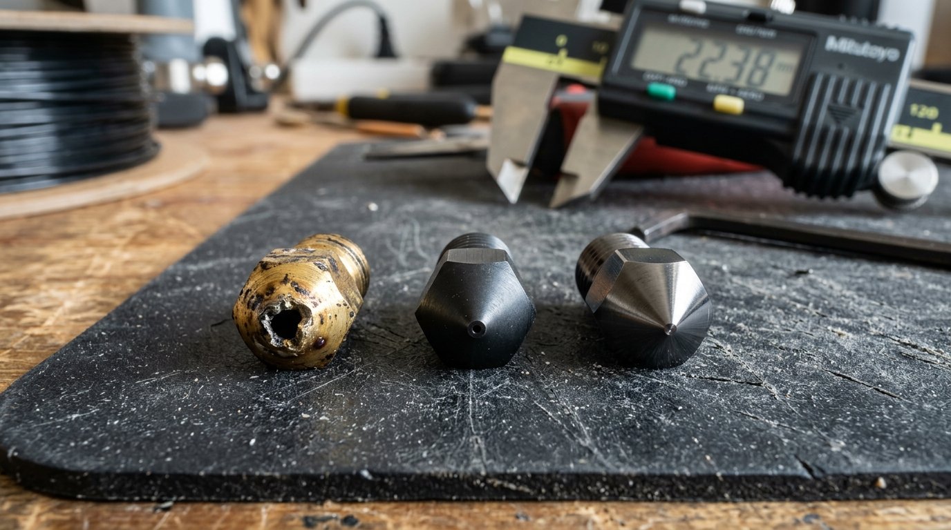
Figure 2: Workshop macro inspection comparing an eroded brass nozzle tip blown out by abrasive carbon fiber against intact hardened steel and polished tungsten carbide tips.
Symptoms of a Blown-Out Brass Orifice
Because nozzle wear occurs gradually inside the hotend, users often misdiagnose the resulting print defects as extruder motor faults or wet filament issues. Watch for these distinct mechanical warning signs:
- Sudden Over-Extrusion and Bulging Corners: As the bore diameter drifts from 0.40mm toward 0.60mm, the actual volume of plastic extruded per step expands beyond the slicer's mathematical model, causing severe perimeter bulging and messy infill overlap.
- Loss of Top-Surface Ironing Quality: The flat circular outer face around the nozzle orifice acts as a miniature mechanical trowel that irons the top layer smooth. Abrasive filaments scour this flat shoulder away into a rounded dome, leaving coarse, furrowed tracks across all top surfaces.
- Aggressive Stringing on Retraction: A sharp, precise nozzle exit creates clean pressure release during retraction. Once the orifice lip becomes rounded and uneven, surface tension cannot hold the melt meniscus, resulting in heavy, persistent oozing across travel moves.
Comprehensive Benchmark Matrix: Brass vs Steel vs Carbide
The comparative engineering table below compiles empirical workshop measurements across the primary FDM nozzle materials, detailing thermal conductivity, mechanical hardness, temperature compensation requirements, and abrasive durability:
| Nozzle Material | Thermal Conductivity (W/m·K) | Vickers Hardness (HV) | Abrasive Wear Resistance | Slicer Temp Offset | Max Flow Impact (at 250 mm/s) | Average Cost (USD) | Primary Intended Use |
|---|---|---|---|---|---|---|---|
| Standard Brass (CW614N) | 115 – 125 | 130 – 160 | Poor (<250g CF wear) | 0°C (Baseline) | 100% (Baseline) | $1 – $3 | Standard non-abrasive PLA, PETG, ABS, TPU |
| Hardened Tool Steel (SKD11/A2) | 20 – 30 | 550 – 700 | Excellent (15–25kg+ CF) | +5°C to +15°C | -15% to -25% drop | $12 – $25 | Abrasive filaments at moderate print speeds |
| Tungsten Carbide (WC-Co) | 90 – 110 | 1,800 – 2,200 | Outstanding (50kg+ lifetime) | 0°C to +3°C | 98% – 100% (Near brass) | $45 – $75 | All-in-one universal printing: high speed & abrasive composites |
| Plated Copper / Bi-Metal | 320 – 380 (Body) | 450 – 600 (Tip) | Good to Very Good | 0°C to -5°C | 105% – 115% boost | $25 – $40 | High-flow printing of non-reinforced or light composites |
| Ruby-Tipped Brass Body | 120 (Body) / 20 (Tip) | 2,500+ (Tip Mohs 9) | High (Tip only) | +5°C to +10°C | -5% to -10% drop | $70 – $110 | Abrasive printing; fragile against bed collisions |
"Do not treat nozzle replacement simply as an abrasive armor upgrade. Swapping from brass to hardened steel fundamentally alters your hotend's thermal transfer curve. If you do not raise print temperatures and retune your heater PID loops, the steel nozzle will starve your melt pool at high speeds."
Workshop Hardware & Material Sourcing
Whether you are outfitting a high-speed CoreXY print farm with long-life tungsten carbide tips or stocking up on vacuum-sealed spools of carbon-fiber nylon, quality tooling and fresh filaments directly dictate print reliability. Before paying full retail price for premium wear-resistant nozzles or composite filaments, check our verified 3D Printing Deals & Coupons page for active manufacturer discounts, toolhead bundle savings, and seasonal promo codes.
Tuning for Hardened Steel: Temperature Offsets and PID Calibration
When switching from brass to hardened steel, you must increase your slicer printing temperatures by +5°C to +15°C and run a hotend PID auto-tune to eliminate thermal lag and extruder under-extrusion. Without these compensations, the hotend heating block cannot supply replacement heat fast enough to maintain proper polymer melt flow.
Because the thermal conductivity of tool steel is roughly 25 W/m·K compared to 120 W/m·K for brass, the temperature gradient between the aluminum heater block and the nozzle tip is wider. At idle, heat will eventually soak through the steel to reach thermal equilibrium. However, the moment the extruder motor advances cold filament into the melt zone, that equilibrium collapses.
Setting Slicer Temperature Offsets
To overcome the thermal resistance of hardened steel, adjust your filament print temperature profiles based on travel speeds:
- Low Speed Printing (<60 mm/s): Add +5°C to your standard brass temperature profile. For example, if you print PLA at 205°C on brass, bump the nozzle temperature to 210°C.
- High Speed Printing (150–300 mm/s): Add +10°C to +15°C to ensure sufficient heat penetrates the fast-moving filament core. For PETG-CF, moving from 245°C up to 255°C or 260°C prevents inter-layer delamination and ensures a strong molecular bond.
- Initial Layer Temperature: Keep your first-layer temperature at +10°C above standard to guarantee excellent initial squish and wet-out against the build plate before part-cooling fans engage.
- Part Cooling Fan Adjustments: Tool steel nozzles bleed thermal energy into high-velocity part-cooling drafts much faster than brass. Lower your cooling fan ceiling by 10% to 20% on enclosed printers to avoid chilling the exposed steel nozzle tip below its melting threshold.
Executing an Automated Hotend PID Calibration
The Proportional-Integral-Derivative (PID) algorithm in your 3D printer's firmware controls how electrical wattage pulses through the heater cartridge to hold a target temperature. Because hardened steel absorbs and releases thermal energy at a noticeably different rate than brass, running with old brass PID constants causes the hotend temperature to swing in wide cycles (±4°C to ±8°C), leaving visible horizontal temperature bands across the walls of your print.
You can execute a fresh PID calibration directly through your printer's terminal or web interface using standard firmware commands:
1. Marlin Firmware PID Routine
Send the following G-code command via OctoPrint, Pronterface, or the printer's serial console while the hotend is cold and the part-cooling fan is running at 100%:
M106 S255                ; Turn on cooling fan to simulate real print draft
M303 E0 S230 C8 U1       ; Auto-tune extruder 0 at 230°C for 8 test cycles and apply values
M500                     ; Save newly calculated P, I, and D constants to EEPROM
2. Klipper Firmware PID Routine
In the Mainsail or Fluidd web console, run the native Klipper calibration macro with your target working temperature and fans active:
M106 S255
PID_CALIBRATE HEATER=extruder TARGET=240
SAVE_CONFIG
Running this 5-minute calibration establishes stable, smooth thermal control, holding the hotend within ±0.5°C of your target temperature throughout long printing sessions.
Volumetric Flow Throttling: Compensating for Low Thermal Conductivity
Hardened steel reduces maximum volumetric extrusion flow by 15% to 25% compared to brass, requiring makers to lower their slicer maximum volumetric speed limits to avoid extruder grinding at high printing speeds. Testing and clamping your flow ceiling prevents hotend clogs when running rapid infill lines.
Volumetric speed represents the cubic millimeters of plastic your hotend can reliably melt and push through the nozzle per second (measured in mm³/s). You can calculate volumetric flow using this basic formula:
On a standard high-flow direct-drive toolhead with a 0.40mm brass nozzle, standard PLA typically achieves a maximum melt rate of roughly 18 to 22 mm³/s before the extruder starts skipping steps. When you install an identical geometry hardened steel nozzle without other hardware changes, that ceiling drops to 14–16 mm³/s because the slower heat transfer rate fails to liquefy the incoming solid plastic fast enough.
Calibrating Flow in Modern Slicers
Rather than guessing speeds for every perimeter and infill move, configure your slicer's global volumetric limit directly:
- Open OrcaSlicer, Bambu Studio, or PrusaSlicer and navigate to your filament profile settings.
- Locate the Max Volumetric Speed parameter.
- If your brass profile runs at 18 mm³/s, reduce this limit to 14 mm³/s for hardened steel.
- Run a standardized volumetric speed ladder test (or dynamic flow rate test) to observe the exact point where the extruded plastic transitions from a clean, glossy finish to a rough, matte texture with extruder skipping. Always maintain your working limit at least 10% below that failure threshold to protect your max volumetric speed limits during rapid accelerations.
- To confirm that your flow adjustments maintain dimensional accuracy, run a quick 3D print quality test benchmark coupon before committing to large composite assemblies.
Tungsten Carbide: The Ultimate All-Rounder Upgrade
Tungsten carbide nozzles combine near-brass thermal conductivity of roughly 90 to 110 W/m·K with an extreme hardness of over 1,800 to 2,200 HV, providing virtually permanent abrasive resistance without requiring slicer temperature compromises or volumetric speed throttling. This unique combination of properties makes solid tungsten carbide the gold standard for high-performance desktop additive manufacturing.
Tungsten carbide (WC) is an advanced technical ceramic-metal composite (cermet) created by sintering fine grains of tungsten carbide with a small cobalt or nickel binder matrix under extreme pressure and heat. Unlike surface-coated or inserted nozzles, premium tungsten carbide nozzles are machined from a single monolithic billet of material.
1. Excellent Thermal Transfer Without Temperature Penalties
Unlike hardened steel, tungsten carbide conducts thermal energy almost as efficiently as pure brass. With thermal conductivity exceeding 100 W/m·K, heat transfers from the hotend block into passing filament with minimal thermal resistance. You can run your factory brass temperature profiles, retain your standard maximum volumetric flow limits, and switch between standard PLA and carbon-fiber nylon without adjusting temperature offsets in your slicer.
2. Extreme Industrial Hardness
Registering over 1,800 to 2,200 HV (equivalent to roughly 9 to 9.5 on the Mohs mineral scale), tungsten carbide is second only to natural and polycrystalline diamond in surface wear resistance. Even heavy concentrations of ceramic strontium aluminate glow particles or jagged chopped glass fibers cannot scratch or erode the internal geometry of a tungsten carbide bore. A single high-grade tungsten carbide nozzle will reliably outlast hundreds of kilograms of abrasive filament without widening by even a fraction of a hundredth of a millimeter.
3. High Resistance to Thermal Shock and Mechanical Damage
One notable vulnerability of sapphire or ruby-tipped nozzles is their sensitivity to thermal and mechanical shock. If an automated bed leveling routine presses a brittle ruby tip hard against a textured PEI plate, or if high-speed cold filament jams against the joint, the synthetic gem can crack or dislodge from its brass housing. Solid monolithic tungsten carbide possesses outstanding fracture toughness and thermal shock endurance, shrugging off bed strikes and aggressive wire brush cleaning cycles without chipping or fracturing.
Evaluating Other Options: Plated Copper, CHT, and Ruby Nozzles
Makers seeking specialized performance can also choose from nickel-plated copper nozzles, Core Heating Technology (CHT) splitters, and ruby-tipped assemblies, each designed for specific printing niches. Assessing these alternative configurations ensures you choose the toolhead setup best matched to your workshop budget and materials.
1. Nickel-Plated Copper Alloys
Copper alloy nozzles (such as CuCrZr) deliver unmatched thermal conductivity, reaching between 320 and 380 W/m·K—more than double that of brass. The outer electro-plated nickel coating reduces molten polymer stickiness and prevents high-temperature oxidation above 300°C. While copper alloys soften at high temperatures and will quickly erode when exposed to carbon fiber or glow powders, they represent the ultimate choice for printing high-speed non-abrasive filaments like PLA, standard PETG, ABS, and flexible TPU.
2. Core Heating Technology (CHT) Nozzles
Patented by Bondtech and widely replicated across modern toolheads, CHT nozzles incorporate three or more internal melt channels that split incoming filament into thin ribbons before recombining them at the orifice. This geometric splitting increases surface area contact with the heated metal, boosting maximum volumetric melt rates by 25% to 40%. While early CHT designs were soft brass only, bi-metal CHT nozzles featuring hardened steel inserts inside copper bodies now allow high-flow extrusion of carbon-fiber filaments without sacrificing melt capacity.
3. Ruby and Diamond-Tipped Nozzles
Synthetic gemstone nozzles embed a laser-drilled ruby or polycrystalline diamond (PCD) crystal into a brass or copper carrier body. The gemstone orifice provides near-infinite wear resistance against all abrasive particles. However, because the gem is pressed or crimped into a secondary metal carrier, thermal transfer across the mechanical seam is uneven, often requiring a +5°C to +10°C slicer offset. Furthermore, replacement costs remain high ($70–$110), and the brittle gem tip can shatter if accidentally crashed into a steel bed clip or misaligned calibration sensor.
Maker's Workshop Notes: Dinu's Real Lessons from the Workbench
Dinu's Workshop Note: Practical Lessons from High-Speed Nozzle Testing
In my workshop tests across my direct-drive toolheads and Creality K1 machines, I regularly run high-volume production jobs in abrasive filaments, including Polymaker PA6-CF, Bambu PETG-CF, and heavy strontium-doped glow PLA. Through hundreds of hours of functional testing, I have documented three practical workshop lessons that save substantial calibration time and prevent ruined prints:
- The Hot-Tightening Golden Rule: When swapping between brass, hardened steel, or tungsten carbide nozzles on standard threaded hotends, never perform final tightening with the heatblock cold. The aluminum heater block expands at a much faster rate than the steel or carbide nozzle threads. If you torque the nozzle at room temperature, thermal expansion during your first 250°C print will open a microscopic gap between the nozzle rear face and the internal heatbreak, sending molten filament oozing over the heatblock threads and ruining your heater cartridge wiring. Always snug the nozzle finger-tight cold, heat the hotend to 280°C, hold the heater block firmly with an open-ended wrench, and torque the nozzle to 2.5 to 3.0 Nm using a dedicated preset torque wrench.
- Detecting Internal Under-Extrusion by Surface Gloss: You do not need a digital microscope to know when a hardened steel nozzle is running too cold for your print speed. Watch the surface finish of your extruded parts. When printing glossy polymers like PETG or ABS, a properly heated melt pool lays down shiny, smooth perimeters. If your nozzle enters thermal lag at high speed, the outer walls will suddenly turn dull, dry, and matte. Whenever you see a transition from gloss to matte on long, straight wall segments, bump your hotend temperature by +8°C or reduce your outer wall speed by 25%.
- The Nozzle Swapping Cost Paradox: Many beginners hesitate to spend $50 on a solid tungsten carbide nozzle, opting instead for a $15 hardened steel nozzle or buying multipacks of cheap $2 brass nozzles. In a busy workshop running abrasive filaments, that initial savings quickly disappears. Swapping worn brass nozzles requires heating the hotend, risking stripped heater block threads, burning fingers, and re-running first-layer Z-offset calibrations every few days. Installing one high-quality tungsten carbide nozzle allows you to print PLA at high speed in the morning, switch to carbon-fiber nylon in the afternoon, and run glow filament at night without touching a wrench or tweaking temperature offsets. For any maker printing more than three rolls of composite filament a year, the single-toolhead convenience easily justifies the upfront investment.
Frequently Asked Questions (FAQ)
Will printing with a hardened steel nozzle damage my 3D printer's heater block?
No, a hardened steel nozzle will not damage your heater block if it is installed correctly. However, because steel is much harder than the soft aluminum used in most standard heater blocks, you must be careful not to cross-thread the nozzle during installation. Always thread the nozzle in by hand for the first several turns before applying a wrench, and never exceed 3.0 Nm of torque when hot-tightening.
Can I print standard PLA with a hardened steel or tungsten carbide nozzle?
Yes, you can print everyday PLA with both materials. When using hardened steel, increase your PLA temperature by roughly +5°C (for example, from 205°C to 210°C) to account for thermal resistance. With tungsten carbide, you can use your exact standard brass temperature profile without making any changes in your slicer.
How long does a brass nozzle last when printing carbon fiber filament?
A standard brass nozzle begins showing measurable dimensional wear after printing as little as 150 to 250 grams of carbon-fiber filament. In many workshop tests, a single 1-kilogram spool of PETG-CF or PA-CF will completely destroy a 0.40mm brass nozzle, blowing out the exit bore past 0.70mm and flattening the ironing shoulder.
Do I need to redo my Z-offset after changing my 3D printer nozzle?
Yes, you should always verify and recalibrate your Z-offset after installing any new nozzle. Even across nozzles of the same brand and model, microscopic manufacturing tolerances of 0.05mm to 0.15mm in overall tip length are common. On printers without automated load-cell homing, failing to reset your Z-offset can result in poor bed adhesion or the nozzle scraping against your PEI build plate.
References & External Sources
- Prusa Research Knowledge Base: Different 3D Printer Nozzle Types and Materials — Technical documentation comparing brass, hardened steel, and specialty Nextruder nozzles for FDM printing.
- Bambu Lab Wiki: Hardened Steel vs Stainless Steel Hotend Specifications — Official maintenance and material guidelines for engineering composite and abrasive filaments.
- Klipper 3D Documentation: Hotend PID Calibration Procedures — Reference guide for tuning hotend heating algorithms and temperature stability in high-speed firmware.
- Marlin Firmware Documentation: M303 Hotend and Heated Bed PID Auto-Tune — Official G-code command specification for PID auto-tuning and thermal stability testing.
About the Author: Dinu Suciu
Dinu Suciu is a dedicated 3D printing engineer and maker specializing in functional FDM prototyping, additive mechanical design, and high-performance engineering thermoplastics. In his workshop, Dinu designs, calibrates, and stress-tests industrial-grade mechanisms on modern CoreXY and direct-drive 3D printers, publishing hands-on design tutorials and practical manufacturing guides.
Have questions about your additive manufacturing project or need custom engineering prototypes? Get in touch via the Contact Page.