




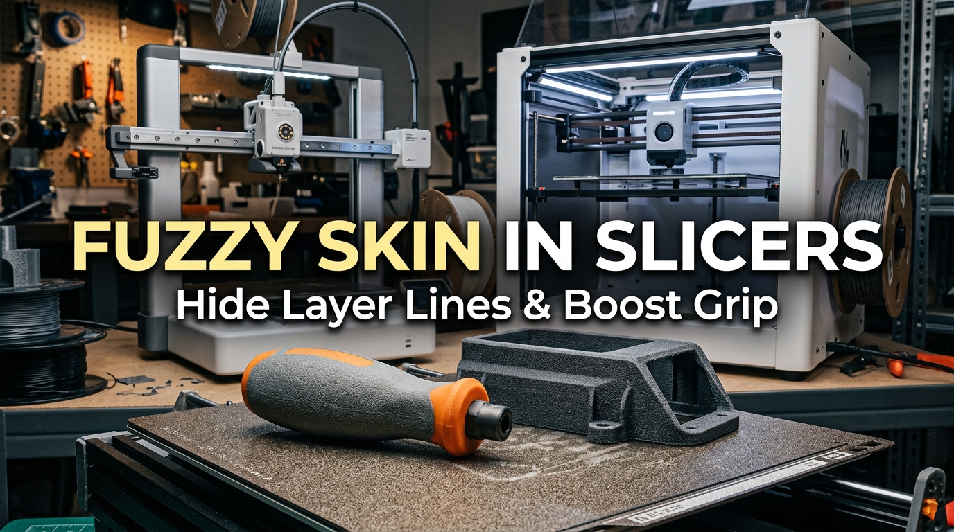
Every 3D printing maker eventually runs into the inherent aesthetic limitation of fused deposition modeling: the visible layer line. Even on properly calibrated high-speed CoreXY machines running at fine 0.12mm layer heights, smooth vertical walls reflect light along horizontal striations. When you add subtle mechanical artifacts like Z-seams, minor ringing ripples, and gloss variations caused by printing speed changes, parts often look distinctly like prototypes rather than finished consumer products. Traditional post-processing remedies like wet sanding, automotive filler primer, or chemical vapor smoothing can transform those surfaces, but they require hours of messy manual labor, toxic solvents, and often destroy critical dimensional tolerances.
Fortunately, modern slicing software offers a software-level solution that bypasses manual labor entirely: Fuzzy Skin. Originally introduced in Cura and now refined across Orca Slicer, Bambu Studio, and PrusaSlicer, Fuzzy Skin fundamentally alters how the printer extrudes outermost perimeter walls. Instead of driving the nozzle along a mathematically straight, continuous toolpath, the slicer introduces controlled, pseudo-random micro-oscillations perpendicular to the wall trajectory. The resulting surface scatters reflected light uniformly, rendering layer steps, Z-seams, and minor vertical banding completely invisible while producing an attractive, textured matte finish reminiscent of sand-cast aluminum or injection-molded stippled polymer.
In this guide, I will break down the underlying mechanics of the Fuzzy Skin perturbation algorithm, provide tested parameter combinations for fine, medium, and heavy textures across PLA, PETG, and ASA, and demonstrate how to use modifier volumes to protect critical mechanical mating faces while texturing exterior grips.
Table of Contents
- The Mechanics of Slicer Fuzzy Skin: How Random Perturbations Disguise Layer Lines
- Decoding Slicer Parameters: Point Distance, Thickness, and Generator Modes
- Selective Texturing: Using Modifier Volumes and Slicer Painting Tools
- Print Time, G-Code Density, and Machine Kinematics Considerations
- Material Selection and Practical Engineering Applications in the Workshop
- Troubleshooting Fuzzy Skin Artifacts: Nozzle Blobs, Gaps, and Wall Adhesion
- Frequently Asked Questions (FAQ)
- References & External Sources
The Mechanics of Slicer Fuzzy Skin: How Random Perturbations Disguise Layer Lines
Slicer Fuzzy Skin injects high-frequency pseudorandom lateral offsets into the outermost perimeter toolpath, replacing specular light reflection with diffuse optical scattering that conceals layer boundaries and minor surface imperfections.
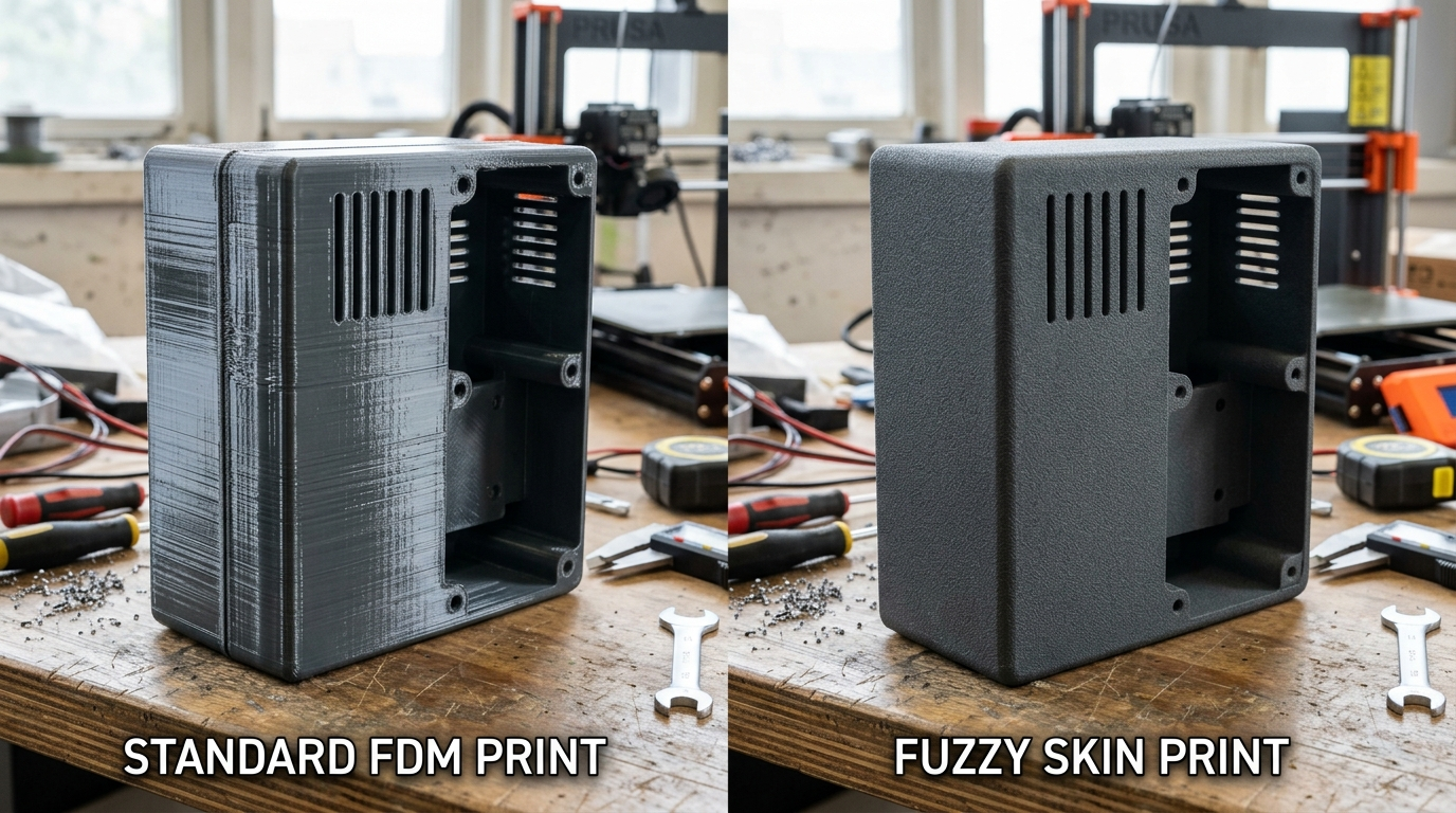
To understand why Fuzzy Skin works so effectively, we have to examine how human eyes perceive 3D printed surfaces. When light strikes a standard FDM print, the smooth, rounded crowns of adjacent extrusion beads act like cylindrical micro-mirrors. Light reflects specularly along the longitudinal axis of each layer bead. Even when layer height is reduced to 0.10mm, this coherent specular reflection highlights the subtle peaks and valleys between consecutive layers. Any slight deviation in extrusion volume, belt tension ripple, or stepper motor pulse causes light to reflect at a slightly altered angle, making minor imperfections jump out to the naked eye.
When you enable Fuzzy Skin in your slicer, the slicing engine intercepts the outermost wall loop during toolpath generation. Rather than issuing a standard linear move from point A to point B, the algorithm subdivides the line into dozens of tiny sub-segments based on your configured point distance. At each sub-coordinate, the slicer applies a randomized vector displacement directed outward or inward perpendicular to the tangent of the wall. When the hot nozzle executes these micro-jitters, it leaves behind a continuous, organic micro-stippled pattern across the external face of the plastic.
This randomized physical texture provides two distinct engineering benefits:
- Optical Light Diffusion: Because the surface lacks any planar or cylindrical alignment, incident light scatters diffusely in every direction. The eye no longer perceives linear reflections, causing layer steps, vertical Z-seams, and ghosting ripples to vanish entirely under standard room lighting.
- Mechanical Friction and Tactile Ergonomics: The microscopic peaks and valleys increase the surface area of contact against human skin or rubberized gloves. For handheld tools, electronics housings, camera mounts, and walking cane handles, this stippled profile provides reliable non-slip grip even when wet or coated in workshop dust.
Maker's Workshop Note
In my workshop tests on my Creality K1 and Bambu Lab P1S printing functional multimeter enclosures with Sunlu PLA+ and Polymaker ASA, standard smooth walls showed noticeable vertical ringing around cutout vents at 250 mm/s. Re-slicing with a fine Fuzzy Skin (0.15mm thickness, 0.6mm point distance) completely masked the ringing while eliminating the need for 45 minutes of sanding and spray painting.
Decoding Slicer Parameters: Point Distance, Thickness, and Generator Modes
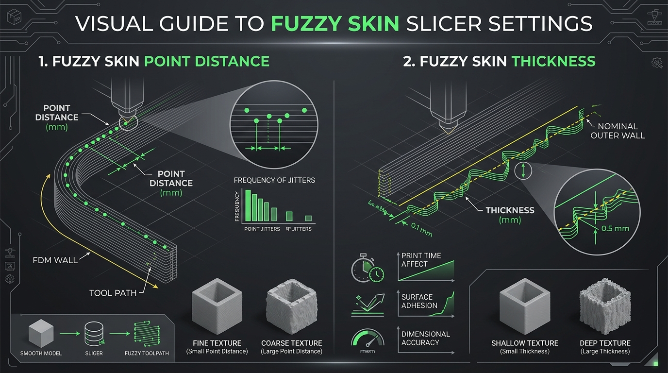
Mastering Fuzzy Skin requires balancing two primary geometric variables: Fuzzy Skin Point Distance, which controls texture frequency, and Fuzzy Skin Thickness, which governs texture depth and dimensional expansion.
Modern slicers like Orca Slicer, Bambu Studio, PrusaSlicer, and Ultimaker Cura expose several parameters that define the morphology of the generated texture. Understanding how these values interact prevents prints from turning into rough sandpaper or failing due to nozzle clogging:
1. Fuzzy Skin Point Distance
Fuzzy Skin Point Distance (measured in millimeters) dictates the average spacing along the perimeter between consecutive random direction changes. In simple terms, it controls the frequency or resolution of the texture:
- Low Point Distance (0.2mm – 0.4mm): Generates an extremely dense, high-frequency texture. While this produces a delicate, velvet-like finish, it creates massive G-code files and can overwhelm older 8-bit or underpowered 32-bit motion controllers with excessive command buffers.
- Balanced Point Distance (0.5mm – 0.8mm): The sweet spot for general workshop printing on modern 32-bit CoreXY machines. It yields a natural, cast-iron or sand-cast texture without excessive toolhead vibration.
- High Point Distance (1.0mm – 1.5mm): Results in a broader, wavy, or hammered-metal appearance. Useful for large architectural planters or decorative cosplay armor pieces.
2. Fuzzy Skin Thickness
Fuzzy Skin Thickness (measured in millimeters) defines the maximum amplitude of the lateral deviation from the nominal wall path. This controls the depth or roughness of the texture:
- Subtle Texturing (0.10mm – 0.15mm): Adds just enough micro-roughness to eliminate specular glare and hide layer lines while keeping exterior dimensions within standard manufacturing tolerances (±0.15mm).
- Standard Grip Texturing (0.20mm – 0.30mm): Produces a prominent, tactile stippled finish ideal for drill handles, screwdriver grips, and rugged equipment cases.
- Heavy / Aggressive Texturing (0.40mm – 0.60mm): Creates deep, chunky ridges. Caution is required here: aggressive thickness settings can cause thin perimeters to delaminate or result in stringy filament whisps if printing speeds exceed nozzle melt flow limits.
3. Slicer Placement Modes (Contour vs. Contour and Hole)
Most slicers allow you to designate which perimeters receive the fuzzy treatment:
- Contour: Applies fuzzy skin exclusively to the outermost boundary of the model. Internal cutouts, screw holes, and bearing bores remain smooth and dimensionally accurate. In most functional workshops, this is the recommended baseline.
- Contour and Hole: Textures both the external boundary and internal cylindrical or polygonal voids. Use this mode only when internal cavities require grip (such as a flashlight holder or tool scabbard), and remember to enlarge hole diameters in CAD to account for inward extrusion growth.
- All Walls: Applies random micro-moves to every perimeter, including internal wall loops behind the outer skin. This mode is rarely desirable because it increases print duration, weakens structural wall bond integrity, and consumes unnecessary G-code bandwidth without visible benefit.
| Texture Profile | Point Distance (mm) | Thickness (mm) | Recommended Wall Speed | Aesthetic / Functional Result | Recommended Materials |
|---|---|---|---|---|---|
| Fine Matte Disguise | 0.50 – 0.60 | 0.10 – 0.15 | 60 – 80 mm/s | Smooth cast-polyurethane appearance; layer lines vanish with minimal dimensional growth. | PLA+, Matte PLA, PETG |
| Medium Tool Grip | 0.60 – 0.80 | 0.20 – 0.30 | 45 – 65 mm/s | Standard stippled power-tool texture; provides secure non-slip traction for handheld equipment. | PLA Pro, PETG, ABS, ASA |
| Heavy Rugged Shell | 0.80 – 1.20 | 0.40 – 0.50 | 35 – 50 mm/s | Aggressive, chiseled stone or truck bed-liner finish; highly durable against scratches and drops. | PETG-CF, ASA, TPU 95A |
| Flexible Tactile Bead | 0.40 – 0.60 | 0.20 – 0.25 | 25 – 40 mm/s | Rubberized tire-tread feel on flexible prints; dampens vibration on drone landing gear and camera mounts. | TPU (85A – 95A) |
Selective Texturing: Using Modifier Volumes and Slicer Painting Tools
Selective Fuzzy Skin texturing uses slicer modifier geometries or brush painting to restrict randomized toolpaths strictly to external grip areas while leaving critical holes, sliding joints, and bearing seats smooth and dimensionally precise.
One of the most common pitfalls makers experience with Fuzzy Skin is applying it globally to an entire functional part. If you design a split electronics enclosure with snap-fit locking tabs, precision M3 counterbores, or internal sliding PCB guide rails, applying global fuzzy skin will deposit bumpy plastic on those contact faces. The snap joints will bind, the PCB will fail to slide into its groove, and the lid will leave an uneven perimeter gap.
To achieve professional engineering results, you must apply texturing selectively. Modern slicers provide two robust methods to accomplish this:
Method 1: Slicer Modifier Shapes (Primitives and Custom Meshes)
In Orca Slicer, Bambu Studio, or PrusaSlicer, you can right-click your model on the build plate and choose Add Modifier -> Cylinder / Box / Sphere (or load a secondary STL exported from CAD):
- Position and scale the modifier volume so it intersects only the specific face or handle zone where texture is desired.
- In the left-hand process panel, select the modifier volume.
- Scroll down to the Fuzzy Skin section under Quality or Others.
- Change Fuzzy Skin from None to Contour, and dial in your desired Thickness and Point Distance parameters specifically for that sub-volume.
- Slice the model. The slicer will keep the main body's perimeters completely smooth, applying the randomized stippled path exclusively where the modifier overlaps the model's outer skin.
Method 2: Fuzzy Skin Painting Tool
Recent releases of Bambu Studio and Orca Slicer feature an interactive Fuzzy Skin Painting tool located in the top toolbar (alongside Seam and Support painting):
- Select your model, click the Fuzzy Skin Paint icon, and set your brush shape to circular or spherical.
- Adjust brush diameter and angle sensitivity.
- Paint directly across the 3D viewport over the ergonomic sections of your handle or enclosure face.
- Set the global Fuzzy Skin mode to None (Allow Paint). When sliced, only the highlighted facets receive the fuzzy perturbation, leaving adjacent precision interfaces untouched.
"Fuzzy Skin should be treated like knurling in traditional machining. You wouldn't knurl the internal bore of a bearing housing or the mating threads of a bolt; you apply texture selectively where human hands interface with the tool, keeping internal functional datum planes clean and true." — Dinu Suciu, Founder of 3D Print Book
Print Time, G-Code Density, and Machine Kinematics Considerations
Enabling Fuzzy Skin increases G-code file size and toolhead directional changes, requiring proper outer wall speed reductions and firmware input shaping to avoid frame resonance and stepper motor overheating.
Because Fuzzy Skin breaks long, smooth perimeter vectors into hundreds of micro-segments, it places unique computational and mechanical demands on your 3D printer. Understanding these factors ensures your machine runs smoothly without buffer underruns or premature mechanical wear:
1. G-Code Buffer Bandwidth and File Size
A standard 100mm cylindrical container sliced at 0.20mm layer height might generate 5 to 10 megabytes of G-code. With fine Fuzzy Skin enabled (0.4mm point distance), that exact same container can expand to 35 to 60 megabytes because every millimeter of outer perimeter requires dozens of explicit G1 X/Y coordinate lines. On modern printers running Klipper, RepRapFirmware, or proprietary Linux-based controllers (like the Bambu Lab X1/P1 series or Creality K1), onboard processors parse these dense command streams effortlessly. However, on older 8-bit printers streaming prints over USB serial via OctoPrint, high-frequency G-code can saturate serial baud rates, causing the nozzle to stutter and deposit melted plastic blobs. If running an older machine, keep point distance above 0.7mm to conserve serial bandwidth.
2. Kinematic Chatter and Accelerometer Input Shaping
Because the toolhead continuously jerks back and forth at high frequency, Fuzzy Skin introduces rapid micro-accelerations into your gantry belts and carriage linear rails. On rigid CoreXY machines with tuned Input Shaping (resonance compensation), the firmware smooths stepper pulses effectively. However, running outer wall speeds above 100 mm/s with heavy fuzzy skin settings can cause noticeable frame vibration and audible motor buzzing. To protect your mechanics and maintain clean extrusion, cap your Outer Wall Speed between 45 mm/s and 70 mm/s when Fuzzy Skin is active.
3. Impact on Total Print Duration
A common misconception among makers is that Fuzzy Skin doubles or triples total print time. In practice, because Fuzzy Skin applies strictly to the single outermost perimeter loop (leaving inner wall loops, infill, and solid top/bottom layers untouched), the net increase in print time is surprisingly modest. On typical functional enclosures, enabling Fuzzy Skin adds only 5% to 12% to total print duration. When compared to the hours required for manual scraping, sanding, and spray painting, this small slicing time penalty is an overwhelming net efficiency gain.
Material Selection and Practical Engineering Applications in the Workshop
Different FDM polymers react distinctly to Fuzzy Skin perturbations: PLA and ASA yield crisp, non-reflective matte surfaces, PETG transforms from glossy to opaque, and TPU delivers high-traction rubberized ergonomics.
The visual and tactile outcome of Fuzzy Skin depends heavily on the polymer chemistry, melting viscosity, and cooling rate of your chosen filament:
1. Standard PLA and PLA Pro
PLA has high tensile modulus and sharp corner reproduction due to its rapid cooling characteristics. When printed with a medium Fuzzy Skin profile (0.20mm thickness, 0.60mm point distance), PLA produces crisp, sharp micro-ridges that closely resemble molded nylon or sand-cast metal. Furthermore, matte PLA filaments (like Polymaker PolyTerra) combined with Fuzzy Skin achieve a dead-flat sheen that hides layer lines so thoroughly that non-makers often mistake the parts for injection-molded commercial products.
2. PETG (Polyethylene Terephthalate Glycol)
Standard PETG is notoriously glossy and prone to highlighting surface scratches, greasy fingerprints, and seam flaws. Applying Fuzzy Skin diffuses PETG's high surface reflectivity, turning glossy parts into an attractive satin finish. Furthermore, because PETG exhibits slight surface stickiness during cooling, fuzzy textures on PETG feel remarkably grippy, making it an excellent choice for outdoor radio enclosures, bicycle light brackets, and garden hose adapters.
3. ABS and ASA (Acrylonitrile Styrene Acrylate)
ASA is our go-to engineering material for automotive interior and outdoor industrial brackets due to its UV resistance and 100°C glass transition threshold. When printed on an enclosed printer like the Creality K1 or Bambu Lab P1S, ASA's natural matte finish pairs seamlessly with Fuzzy Skin. It creates a pebbled, leather-like grain that matches original equipment manufacturer (OEM) automotive dashboard plastics, allowing aftermarket gauge pods and phone cradles to blend into car interiors without looking 3D printed.
4. TPU and Flexible Filaments
Applying Fuzzy Skin to 95A or 85A TPU yields remarkable functional benefits. Smooth TPU parts often feel clammy or slick against sweaty palms. Introducing a fine fuzzy texture creates a micro-ribbed elastomeric profile that feels similar to molded rubber tire tread. We regularly use this technique for custom soldering iron grips, drone bumper guards, and vibration-dampening feet on tabletop power supplies.
Troubleshooting Fuzzy Skin Artifacts: Nozzle Blobs, Gaps, and Wall Adhesion
Resolving Fuzzy Skin print defects involves verifying filament dryness, increasing hotend melt temperature by 5°C to maintain inter-perimeter bonding, and calibrating retraction to eliminate localized stringing.
While Fuzzy Skin is generally reliable once configured, subtle slicing and thermal issues can occasionally produce defects. Here are the three most common issues and how to resolve them:
1. Weak Outer Wall Adhesion (Shell Delamination)
If you drop a fuzzy-skinned part and the textured outer perimeter peels away from the smooth inner wall like an onion skin, the outer bead failed to fuse thermally to the inner perimeter. Because the nozzle slows down and oscillates outward during fuzzy extrusion, the molten plastic can cool down prematurely before pressing firmly against the inner wall. To fix this:
- Increase your hotend temperature by 5°C to 10°C to improve polymer melt pool fluidity.
- Slightly increase your Outer Wall Flow Ratio (by 3% to 5%) to ensure adequate squish between adjacent perimeter beads.
- In Orca Slicer, ensure your wall printing order is set to Inner-Outer (IO) so the fuzzy outer wall presses against a warm, freshly extruded inner anchor.
2. Fine Whisps and Nozzle Fur on Intricate Features
If your part develops fine, cobweb-like stringing or fuzzy "fur" extending off overhangs and sharp corners, the hotend is oozing during rapid micro-direction reversals. This is almost always exacerbated by wet filament. Water vapor boiling inside the nozzle creates micro-popping that throws tiny droplets outward during rapid vibration. Thoroughly dry your spool in a filament dryer before printing. If stringing persists, lower print temperature by 5°C and verify your retraction distance is tuned correctly.
3. Dimensional Creep on External Holes and Cutouts
If your M3 or M5 bolt heads fail to seat into recessed counterbores, you likely have Fuzzy Skin set to Contour and Hole instead of Contour. If you must texture internal holes, compensate in your slicer by applying an X-Y Hole Compensation of +0.15mm to +0.25mm, or design the holes 0.3mm larger in your CAD software to absorb the inward textured jitter.
Frequently Asked Questions (FAQ)
Q1: Does Fuzzy Skin weaken the structural mechanical strength of a 3D printed part?
In tensile and bending tests, Fuzzy Skin does not measurably weaken structural integrity, provided you print with at least 3 or 4 wall loops. Because the random perturbations are applied solely to the outermost perimeter, the load-bearing inner perimeters and solid infill core remain completely solid and continuous. However, for thin single-wall vases or parts with only 1 perimeter, fuzzy skin can reduce watertightness and tear resistance.
Q2: Can I use Fuzzy Skin with abrasive carbon fiber or glass fiber filaments?
Yes, Fuzzy Skin works exceptionally well with carbon fiber filled filaments like PETG-CF or PA-CF. CF filaments already have a naturally matte, stone-like appearance; combining them with a subtle Fuzzy Skin profile (0.10mm thickness) completely obliterates layer lines, yielding a part that looks and feels like a solid CNC-machined graphite block.
Q3: Why doesn't Fuzzy Skin appear on the top or bottom flat surfaces of my print?
Fuzzy Skin algorithms operate strictly on vertical and sloped perimeter wall loops. Top and bottom horizontal faces are formed by solid infill toolpaths (such as monotonic line or rectilinear patterns) and are not processed by wall perturbation code. To texture flat top surfaces, use slicer features like Ironing with a high line spacing or design embossed stippled textures directly into your CAD model.
Q4: How does Fuzzy Skin affect printer noise during operation?
Because Fuzzy Skin causes toolhead steppers to rapidly oscillate back and forth, you will hear a distinct buzzing or chattering sound during outer wall passes. On printers with silent Trinamic drivers, this is entirely normal and represents the rapid micro-stepping changes dictated by the dense G-code.
Q5: Which slicers currently support the Fuzzy Skin feature?
Fuzzy Skin is supported natively in Orca Slicer, Bambu Studio, PrusaSlicer, Ultimaker Cura, and SuperSlicer. Orca Slicer and Bambu Studio offer the added advantage of the interactive Fuzzy Skin Paint brush tool, allowing makers to paint texture selectively onto specific model facets without creating separate geometric modifier meshes.
References & External Sources
- Prusa Knowledge Base: Complete Guide to Fuzzy Skin Parameters
- Bambu Lab Wiki: Fuzzy Skin Modes and Slicer Painting Setup
- OrcaSlicer Official GitHub Wiki & Advanced Quality Settings
- Ultimaker Cura Open Source Repository & Surface Finish Documentation
About the Author: Dinu Suciu
I am Dinu Suciu, founder and lead technician at 3D Print Book. Operating an FDM-focused 3D printing workshop, I specialize in fine-tuning slicer algorithms, testing engineering polymers, and optimizing high-speed CoreXY machines. My goal is to provide practical, fluff-free technical guides that help makers build stronger, better-looking 3D prints. If you have questions about slicer calibration or custom FDM projects, feel free to reach out via our contact page.