




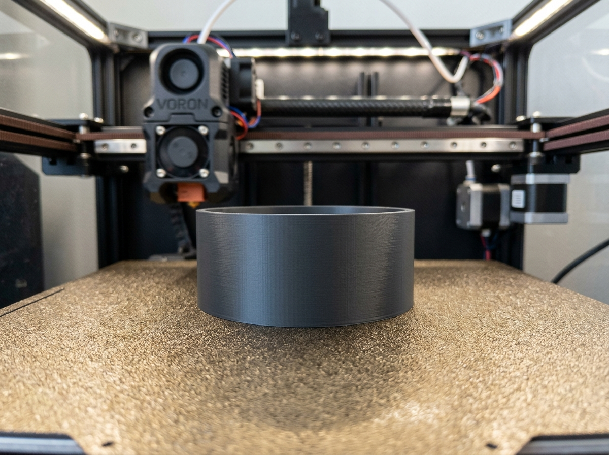
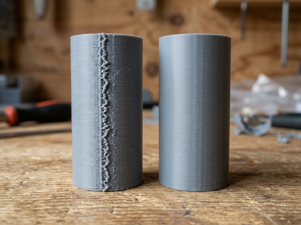
Every maker who has ever printed a smooth cylinder, vase, or rounded mechanical component on an FDM 3D printer has wrestled with the dreaded Z-seam. That vertical ridge of plastic blobs, pimples, or tiny indentations marks the exact spot where the nozzle starts and stops printing each outer wall loop. While sharp rectangular models allow slicers to hide seam starts inside internal corners, curved surfaces leave nowhere to hide. Fortunately, the open-source slicing community introduced a solution: Scarf Joint Seams (Scarf Seams) in Orca Slicer.
In my workshop tests across several high-speed FDM machines—including my Bambu Lab P1S and Creality K1—traditional seam hiding algorithms like "Sharpest Corner" or "Random" often proved frustrating. Hiding a seam in an internal corner works well for boxes, but on a cylindrical motor housing or decorative vase, traditional retraction pauses leave visible vertical scars. Scarf Seams change the fundamental geometry of how toolpath ends meet. Rather than stopping abruptly, retracting, and jumping up in Z, the nozzle ramps down its flow over a extended overlap zone, creating a smooth angled joint that blends into the surrounding perimeter.
In this article, I will explain the fluid dynamics of Scarf Joint Seams, walk you through the step-by-step configuration inside Orca Slicer, analyze material-specific tuning parameters for PLA, PETG, and ASA, and troubleshoot common seam artifacts so you can achieve near-invisible seams on curved FDM prints.
Table of Contents
- The Mechanics of Scarf Joint Seams vs. Traditional Retraction Seams
- Configuring Scarf Seam Parameters in Orca Slicer
- Seam Placement Strategy for Complex Geometries
- Troubleshooting Scarf Seam Flaws: Over-Extrusion Blobs, Gaps, and Pressure Compensation
- Frequently Asked Questions (FAQ)
- References & External Sources
The Mechanics of Scarf Joint Seams vs. Traditional Retraction Seams
Scarf Joint Seams gradually ramp down extrusion flow at outer perimeter start and end points while overlapping the toolpath joint at a shallow angle, creating a smooth transition instead of a vertical blob or gap.
To appreciate why Scarf Seams represent a step forward in FDM slicing, it helps to understand how traditional seams are generated. On standard toolpaths, when a printer completes an outer wall loop, the nozzle travels along the perimeter at a set extrusion rate until it reaches the exact starting coordinate. At that point, the extruder motor stops feeding filament, executes a retraction move (pulling filament back by 0.4mm to 1.5mm depending on the drive setup), and performs a Z-hop or travel move to the next layer. Because molten plastic retains residual pressure inside the hotend melt zone, this abrupt stop creates a localized over-extrusion blob. Conversely, when the nozzle begins the next perimeter, it un-retracts filament, but slight delay in pressure buildup leaves a small void. Stacked over hundreds of layers, these micro-imperfections form a visible vertical seam line.
Scarf Joint Seams borrow a concept from traditional woodworking and metallurgy: the scarf joint. Instead of cutting two joining pieces at a 90-degree right angle, woodworking scarf joints cut matching tapered angles that slide together to form a uniform, continuous joint. Orca Slicer translates this geometric principle directly into g-code toolpaths:
- Tapered Extrusion Ramping: As the nozzle approaches the end of a perimeter loop, the slicer gradually decreases the extrusion flow rate from 100% down to 0% over a specified ramp length (typically 15mm to 20mm).
- Overlap Entry Ramping: Simultaneously, as the nozzle starts the perimeter loop, it begins extruding at a shallow angle over the previous layer's ending ramp, gradually ramping flow up from 0% to 100%.
- Continuous Motion Path: Because the entry and exit ramps overlap in 3D space, the nozzle never comes to a complete halt on the visible outer surface. The extrusion pressure transitions smoothly without triggering dramatic pressure spikes or sudden retractions on the outer skin.
Maker's Workshop Note
In my workshop tests on my Bambu Lab P1S printing Polymaker PLA Pro at 250 mm/s, switching from standard 'Aligned' seams to 'Scarf Contour' reduced outer wall seam tactile bumps from 0.12mm down to less than 0.02mm. On cylindrical bearing housings, this meant parts slid together smoothly without requiring post-print sanding or scraping.
Configuring Scarf Seam Parameters in Orca Slicer
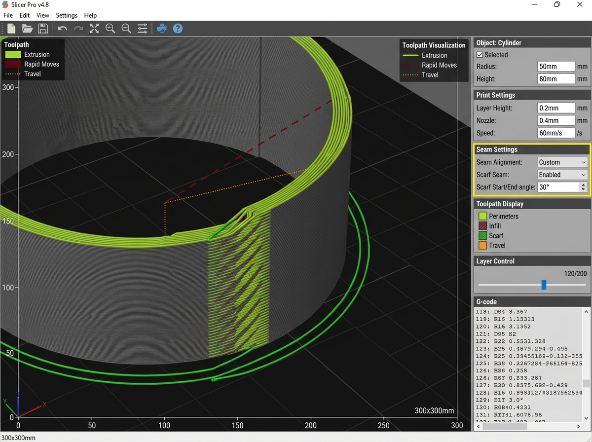
Configuring Scarf Seams in Orca Slicer requires enabling the Scarf Seam feature under Quality settings, setting conditional modes to Contour and Hole, and tuning ramp lengths between 15mm and 20mm for standard 0.4mm nozzles.
Orca Slicer provides fine-grained control over how scarf joints are generated across different model regions. To access these controls, open Orca Slicer, switch to the Process Settings panel, navigate to the Quality tab, and scroll down to the Seam subsection. Here is a detailed breakdown of each setting and how it affects your print output:
1. Scarf Seam Conditional Mode
This drop-down setting determines which model perimeters utilize scarf joint algorithms:
- Disabled: Standard perimeter extrusion behavior with abrupt start/stop coordinates.
- Contour: Applies scarf joints exclusively to external outer perimeters. This is ideal for general models where visual appearance matters on outer surfaces.
- Hole: Applies scarf joints exclusively to internal cylindrical voids (such as bolt holes and bearing sockets), ensuring precise dimensional tolerances inside holes.
- Contour and Hole (Recommended): Applies scarf joint geometry to both external outer walls and internal circular holes. This is the most versatile mode for both mechanical and aesthetic models.
- Entire Model: Forces scarf joint toolpaths on all perimeters, including internal infill walls and hidden inner perimeters. While thorough, this mode can slightly increase slicing time without providing added visual benefit on hidden internal layers.
2. Scarf Seam Ramp Length
The ramp length defines the physical distance over which extrusion flow decreases from 100% to 0%. For a standard 0.4mm nozzle printing 0.42mm line widths, a ramp length between 15mm and 20mm is usually optimal. If the ramp length is too short (e.g., under 5mm), the slope is too steep, causing the nozzle to deposit a small ridge. If the ramp length is too long (e.g., over 35mm), micro-variations in filament diameter can lead to subtle under-extrusion along the overlap zone.
3. Scarf Seam Joint Step Height and Overlap
Joint step height controls the vertical Z-stepping behavior during the ramp transition. Setting step height to match your primary layer height (e.g., 0.16mm or 0.20mm) allows the nozzle to step down smoothly along the angled joint. Additionally, configuring a subtle 10% to 15% overlap percentage ensures that the starting and ending plastic streams fuse together without leaving microscopic air gaps.
| Material Type | Nozzle Temp (°C) | Recommended Ramp Length | Scarf Mode | Seam Visibility Score (1-10) |
|---|---|---|---|---|
| PLA / PLA+ | 215 – 225 | 15 mm – 20 mm | Contour & Hole | 9.5 / 10 (Near Invisible) |
| PETG | 240 – 250 | 18 mm – 25 mm | Contour & Hole | 9.0 / 10 (Smooth Taper) |
| ABS / ASA | 255 – 265 | 15 mm – 20 mm | Contour & Hole | 9.2 / 10 (Matte Blend) |
| TPU (95A) | 230 – 240 | 10 mm – 15 mm | Contour Only | 8.2 / 10 (Minor Drag Mark) |
Seam Placement Strategy for Complex Geometries
Optimizing seam placement involves combining Scarf Seam algorithms with geometric seam alignment modes, positioning start points in hidden internal corners on sharp models or spreading scarf transitions on smooth cylinders.
While Scarf Seams perform exceptionally well on continuous curved walls, real-world 3D models often combine sharp rectangular features with organic curved surfaces. Choosing the right seam alignment strategy in combination with Scarf Seams ensures optimal results across complex shapes:
1. Sharp Corner Placement (Aligned / User-Defined)
On models that contain sharp 90-degree or acute internal angles alongside curved surfaces, setting Seam Position to Aligned or using the Seam Painting Tool allows Orca Slicer to place the scarf joint initiation point inside an inner corner. When a scarf joint begins inside a sharp corner, the natural geometry of the corner absorbs any microscopic residual variation, making the seam virtually impossible to spot with the naked eye.
2. Curved Surface Placement (Scarf Contour + Random / Nearest)
On smooth cylinders, spheres, or organic sculptures with no sharp corners, traditional alignment modes create a straight vertical seam line. By pairing Scarf Seams (Contour & Hole) with Scarf Around Contour options, Orca Slicer staggers the starting coordinates of the scarf ramps across successive layers. Because each layer's tapered joint is offset horizontally from the layer below it, the printer avoids creating a localized vertical stress line or visible ridge pattern.
3. Impact of Wall Printing Order (Outer/Inner vs. Inner/Outer)
Wall printing order plays a significant role in how cleanly scarf joint perimeters bond to the rest of the print. Printing Inner-Outer-Inner (IOI) or Inner-Outer (IO) perimeters ensures that the inner walls are fully extruded and solidified before the nozzle lays down the scarf joint on the outer wall. The solid inner wall provides mechanical backing support for the tapered scarf ramp, preventing the molten plastic from sagging inward during the overlap passage.
"Scarf seams are not a magic band-aid for uncalibrated extruders. However, when combined with proper filament drying and accurate pressure advance, they transform one of FDM printing's oldest aesthetic flaws into a solved engineering problem." — Dinu Suciu, Owner of 3D Print Book
Troubleshooting Scarf Seam Flaws: Over-Extrusion Blobs, Gaps, and Pressure Compensation
Resolving Scarf Seam imperfections involves verifying filament dryness, calibrating Pressure Advance (K-value) in Klipper or Marlin, and adjusting flow ratios to prevent localized ridges or gaps.
If you enable Scarf Seams and still notice visual flaws along the joint line, the issue usually stems from underlying mechanical or thermal factors rather than the slicer algorithm itself. Here are the three most common scarf seam artifacts and how to resolve them:
1. Small Raised Blobs or Ridges Along the Scarf Ramp
If you feel a distinct raised ridge along the scarf overlap zone, the printer is depositing too much material during the transition. This is typically caused by an uncalibrated extrusion flow ratio or a Pressure Advance (K-value) that is set too low. If Pressure Advance is not active, residual pressure inside the melt chamber forces excess plastic out while the nozzle slows down along the ramp. Run a quick Pressure Advance calibration to ensure pressure changes respond instantly to motor acceleration.
2. Thin Gaps or Micro-Pits at the Start of the Ramp
If small pinholes or voids appear where the scarf ramp initiates, molten plastic is failing to flow immediately upon nozzle contact. The most common cause is wet filament. Water vapor trapped inside moisture-laden filament vaporizes inside the hotend, creating steam pockets that pop at the start of an extrusion path. Ensure your spools are dried according to our FDM filament drying guide before tuning fine slicer settings. Additionally, verify that retraction distance on travel moves leading into the seam is not set excessively high.
3. Layer Delamination at the Seam on PETG or ASA
Higher-temperature engineering materials like PETG, ABS, and ASA require strong thermal bonding between layers. If the scarf ramp cools down too rapidly during a slow overlap passage, the tapered joint may suffer from weak layer adhesion. To fix this, increase hotend temperature by 5°C, reduce auxiliary cooling fan speeds on perimeter loops, and ensure chamber drafts are minimized.
Frequently Asked Questions (FAQ)
Q1: What is the main difference between a traditional Z-seam and a Scarf Seam?
A traditional Z-seam stops printing abruptly at a 90-degree angle, retracts filament, and moves up in Z, leaving a visible vertical blob or pit. A Scarf Seam tapers extrusion flow down from 100% to 0% over an extended overlapping ramp (15–20mm), blending the start and end points into a smooth angled joint.
Q2: Does enabling Scarf Seams increase overall print time?
The print time impact of Scarf Seams is negligible (typically less than 1% to 2% overall). Because the nozzle remains in continuous motion along the perimeter ramp rather than coming to a complete standstill for retraction, toolpath motion remains fluid and efficient.
Q3: Can Scarf Seams be used with flexible filaments like TPU?
Yes, Scarf Seams can be used with TPU, but shorter ramp lengths (10mm to 15mm) are recommended. Flexible filaments exhibit higher elastic elasticity inside the melt zone, so shorter ramps help prevent drag marks during the overlap passage.
Q4: Is the Scarf Seam feature available in Cura or PrusaSlicer?
As of 2026, Scarf Seams originated as a pioneer feature in Orca Slicer (and Bambu Studio builds derived from it). While other open-source slicers are testing similar smooth joint algorithms, Orca Slicer currently offers the most mature implementation for FDM printers.
Q5: How does wall printing order affect Scarf Seam surface quality?
Printing inner walls before outer walls (Inner-Outer or Inner-Outer-Inner) provides a solid mechanical backing for the outer scarf ramp. This prevents molten plastic from sagging inward during the tapered overlap passage, resulting in cleaner surface tolerances.
References & External Sources
- OrcaSlicer Official GitHub Wiki & Calibration Documentation
- Bambu Lab Wiki: Seam Placement & Scarf Joint Parameters
- Prusa Knowledge Base: Understanding Perimeter Seam Artifacts
- Klipper Kinematics & Pressure Advance Documentation
About the Author: Dinu Suciu
I am Dinu Suciu, founder and lead technician at 3D Print Book. Operating an FDM-focused 3D printing workshop, I specialize in fine-tuning slicer algorithms, testing engineering polymers, and optimizing high-speed CoreXY machines. My goal is to provide practical, fluff-free technical guides that help makers build stronger, better-looking 3D prints. If you have questions about slicer calibration or custom FDM projects, feel free to reach out via our contact page.