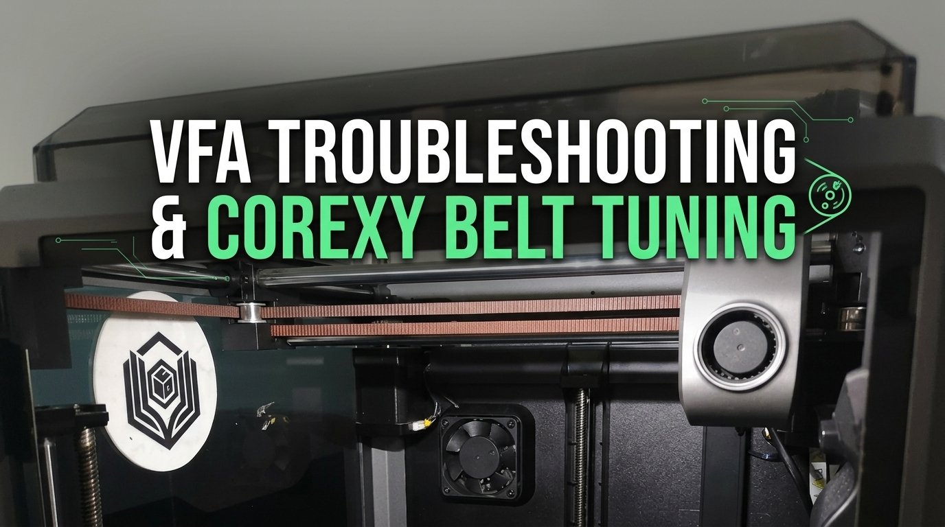
High-speed CoreXY FDM 3D printers have revolutionized desktop manufacturing by allowing us to produce complex geometric parts in a fraction of the time required by traditional bed-slingers. However, as toolhead accelerations push past 10,000 mm/s² and print speeds exceed 250 mm/s, a subtle aesthetic defect often emerges on smooth vertical walls: Vertical Fine Artifacts (VFA). These tightly spaced, repeating vertical ridges can turn an otherwise flawless prototype into a textured surface that catches side lighting and ruins cosmetic appeal.
As the operator of 3D Print Book's production studio, I work daily with enclosed CoreXY motion systems like the Creality K1, K1 Max, Bambu Lab P1S, and custom Voron builds. While ghosting and ringing are dynamic acceleration artifacts that taper off after sharp corners, VFAs are pitch-consistent, continuous micro-patterns that run across entire flat or curved vertical faces. Resolving VFAs requires a deep mechanical understanding of stepper motor harmonics (MRR - Motor Resonance Rippling), ADXL345 accelerometer resonance sweeps, GT2 belt tension alignment, pulley tooth meshing dynamics, and slicer speed threshold mapping. In this comprehensive technical guide, we will break down the exact physics behind VFAs and walk through step-by-step calibration protocols using OrcaSlicer and firmware tools to eliminate them from your FDM prints.
Table of Contents
- What Causes Vertical Fine Artifacts (VFA) on FDM Prints?
- Calibrating Resonance and Belt Dynamics Using ADXL345 Accelerometers
- Speed Thresholds and OrcaSlicer VFA Calibration to Bypass Harmonics
- VFA vs. Ghosting vs. Z-Wobble: Diagnostic Comparison
- Step-by-Step VFA Elimination Checklist
- Frequently Asked Questions (FAQ)
- References & External Sources
1. What Causes Vertical Fine Artifacts (VFA) on FDM Prints?
Vertical Fine Artifacts (VFAs) are periodic vertical line patterns printed along wall perimeters, caused primarily by stepper motor cogging torque harmonics (Motor Resonance Rippling or MRR), belt tooth engagement friction against smooth or toothed pulleys, and unequal tension across the dual-belt CoreXY kinetic gantry.
To understand why VFAs occur, we must examine the mechanical kinematics of a CoreXY motion system. Unlike Cartesian bed-slingers where the X and Y axes are driven independently by separate motors on distinct structural gantries, a CoreXY printer utilizes two stationary stepper motors (typically designated Motor A and Motor B) operating in unison through two continuous GT2 timing belts. The position of the toolhead along the X and Y plane is governed by simultaneous motor rotations:
- Pure X-Axis Movement: Both Motor A and Motor B rotate in the same direction at identical speeds.
- Pure Y-Axis Movement: Motor A and Motor B rotate in opposite directions at identical speeds.
- Diagonal Travel (45°): Only one motor rotates while the second motor remains held stationary under full holding torque.
Because the toolhead position relies on the combined tension and movement of both belts, any mechanical micro-vibration or non-linear velocity ripple generated by either motor or belt path immediately translates into minute positional shifts at the hotend nozzle tip.
Maker's Workshop Note: The Physical Reality of Stepper Cogging & MRR
In my workshop testing on our Creality K1 series printers, I observed that VFAs peak at specific printing speeds—most noticeably between 40 mm/s and 90 mm/s. Standard 1.8° stepper motors have 200 full steps per revolution. As the rotor turns, the internal magnetic poles experience "detent torque" or cogging as teeth pass stator poles. This creates Motor Resonance Rippling (MRR). At low speeds, microstepping smooths out this transition, but physical magnetic reluctance torque fluctuations still send tiny rotational pulses into the drive pulleys. If your belt tension is mismatched, these tiny pulses flex one belt more than the other, carving micro-stripes spaced exactly 1.0mm to 2.0mm apart onto outer perimeters.
The Three Key Drivers of VFA
Through extensive diagnostic logging, mechanical engineers and FDM practitioners categorize VFAs into three main root causes:
- Stepper Motor Detent & Cogging Torque (MRR - Motor Resonance Rippling): Every hybrid permanent-magnet stepper motor produces small torque variations throughout each full step rotation. At certain rotational velocities, the frequency of these magnetic pulses matches the structural resonant frequency of the gantry, amplifying toolhead oscillation.
- GT2 Belt Tooth Engagement (Pulley Pitch Ripples): GT2 timing belts feature a 2.0mm tooth pitch. As the belt wraps around drive pulleys and idler bearings, the rubber teeth seat into pulley grooves. If smooth idler bearings are used on the toothed side of the belt instead of properly sized toothed idlers, the teeth bump across the smooth bearing surface, generating mechanical ripples with a strict 2.0mm period on vertical walls.
- Asymmetric Belt Tension & Gantry Skew: CoreXY gantries rely on equal tension in both A and B loops. If Belt A is significantly tighter than Belt B, the stiffer belt transmits motor vibrations far more efficiently than the slack belt. This creates asymmetric compliance, allowing the toolhead carriage to twist slightly during lateral directional changes.
2. Calibrating Resonance and Belt Dynamics Using ADXL345 Accelerometers
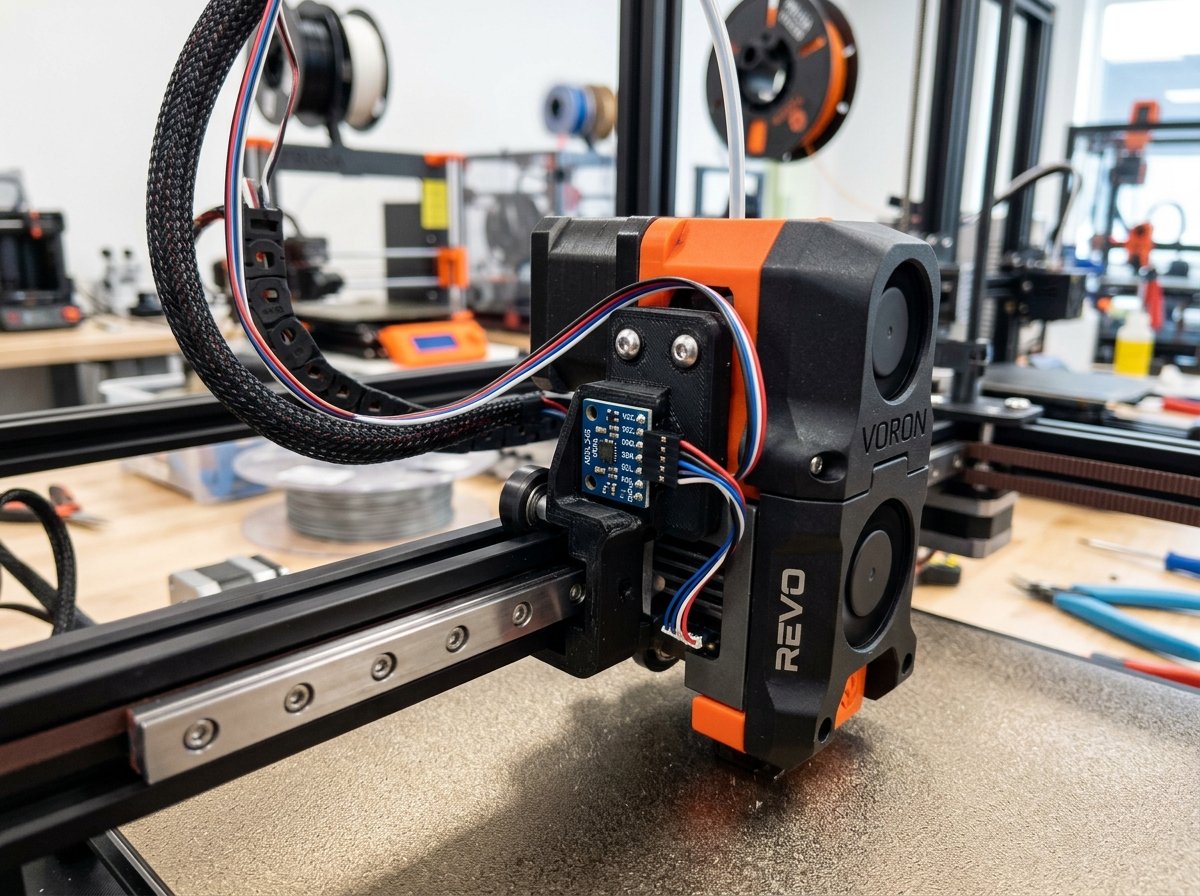
Calibrating mechanical resonance and gantry dynamics accurately requires mounting a MEMS 3-axis accelerometer sensor—typically an ADXL345 module—directly onto the toolhead carriage and build bed, allowing the printer firmware (such as Klipper or Creality OS) to execute automated frequency sweeps to measure structural vibration peaks and calculate Input Shaping compensation curves.
While mechanical belt tensioning establishes baseline gantry squareness and prevents loose belt backlash, dynamic vibration compensation cannot be determined visually. An ADXL345 accelerometer measures real-time gravitational acceleration forces (in Gs) along the X, Y, and Z axes as the firmware shakes the toolhead through a frequency spectrum from 10 Hz to 150 Hz.
Step-by-Step ADXL345 Resonance Sweep Protocol
To perform an accurate dynamic resonance calibration on Klipper, Creality OS (Sonic Pad / Nebula Pad / K1 series), or custom CoreXY builds, follow this structured procedure:
- Mount the Accelerometer Board: Securely fasten the ADXL345 accelerometer PCB module directly to the toolhead housing (for X-axis resonance measurement) or to the print bed assembly (for Y-axis resonance measurement on moving-bed setups). Ensure the sensor is rigidly bolted to avoid false secondary resonance readings.
- Connect to Firmware SPI/USB Interface: Wire the ADXL345 module to the printer motherboard or host MCU (such as a Raspberry Pi or Creality motherboard header) using shielded SPI cabling or a dedicated USB accelerometer bridge.
- Execute Automated Frequency Sweeps: From the Klipper terminal or web dashboard (Mainsail / Fluidd / Creality Web UI), issue the automated calibration command:
SHAPER_CALIBRATE AXIS=Xfollowed bySHAPER_CALIBRATE AXIS=Y - Analyze Spectral Frequency Graphs: The firmware will generate power spectral density (PSD) charts showing the primary resonance frequencies (measured in Hz) and recommended Input Shaper algorithms (such as
mzv,ei, or2hump_ei) along with their corresponding damping ratios. - Save Configuration Parameters: Save the calculated shaper filter settings into your
printer.cfgfile. This dynamic filtering actively neutralizes toolhead vibration bursts before stepper motors receive motion commands.
| Printer Model / Kinematics | Sensor Setup (ADXL345) | Typical Resonance Peak | Optimal Shaper Algorithm | VFA & Resonance Mitigation Notes |
|---|---|---|---|---|
| Creality K1 / K1 Max / K1C | Toolhead PCB Connector / USB G-Sensor | 45 Hz – 65 Hz | MZV or EI |
Automated self-test sweeps identify gantry resonance; belt mechanical tension must be balanced prior to sweep. |
| Bambu Lab P1S / X1C | Built-in Internal Accelerometer | 50 Hz – 70 Hz | Custom Active Compensation | Integrated automated frequency sweep during initial printer calibration sequence. |
| Voron 2.4 / Trident (Custom CoreXY) | Toolhead Mounted ADXL345 (SPI/USB) | 55 Hz – 75 Hz | MZV / 2HUMP_EI |
Dual-axis sweeps detect frame flex; equalizing A/B belt tension shifts resonance peaks higher where dampening is more effective. |
| Creality Ender-3 V3 Series | Creality G-Sensor via Sonic/Nebula Pad | 40 Hz – 55 Hz | MZV |
Reduces corner ringing on fast perimeters; mechanical VFA speed towers required to isolate motor cogging bands. |
For additional details on overall printer setup and diagnostic models, review our guide on 3D print quality tests and calibration models.
3. Speed Thresholds and OrcaSlicer VFA Calibration to Bypass Harmonics
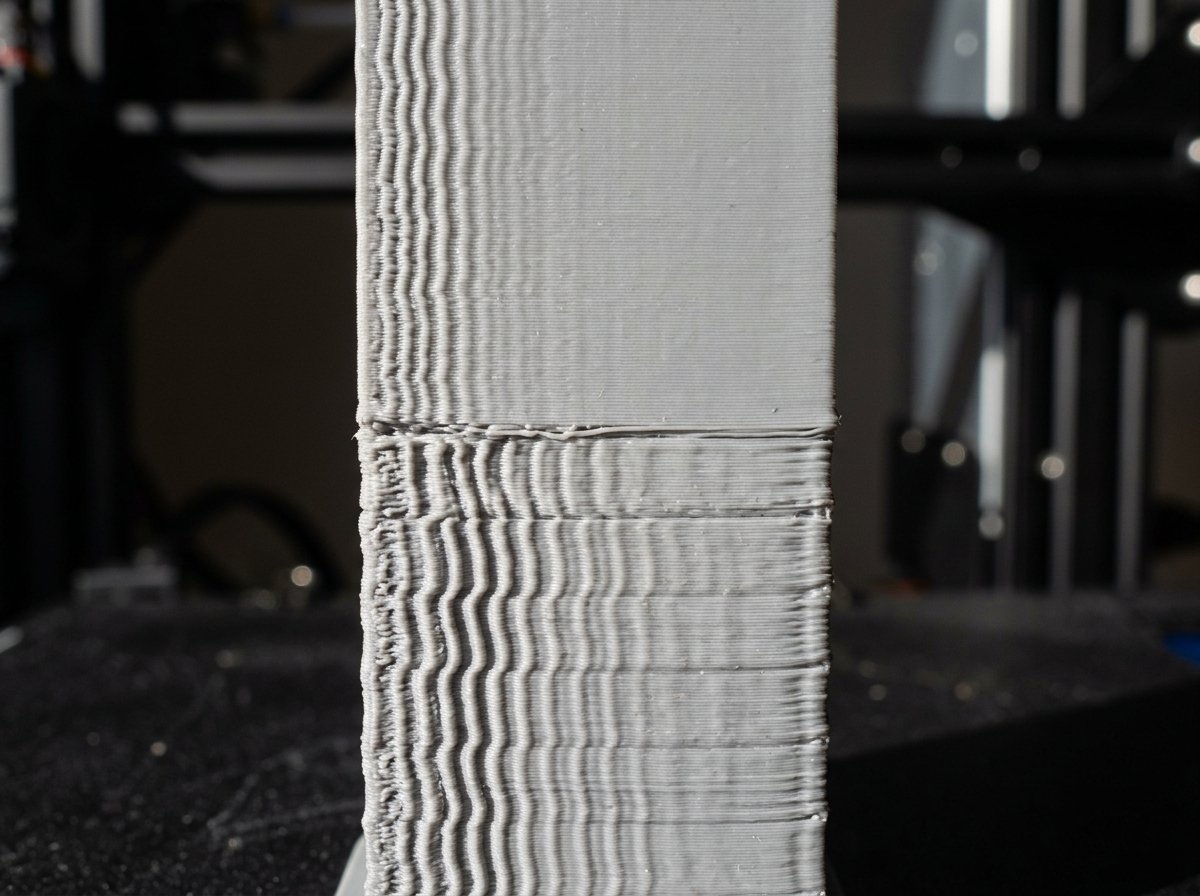
OrcaSlicer provides a dedicated built-in VFA Calibration test tool that automatically generates a multi-tier speed tower with curved, thin-walled geometries, allowing makers to visually identify the precise speed range where motor cogging harmonics and surface ripples disappear.
Because stepper motor cogging frequency scales directly with rotational RPM, motor-induced micro-vibrations occur at predictable speed bands. On most CoreXY printers equipped with 1.8° stepper motors and 20-tooth pulleys, the primary harmonic resonance zone falls between 40 mm/s and 90 mm/s. When printing outer wall perimeters at 50 mm/s, the motor pulses match the mechanical pendulum frequency of the gantry, resulting in heavy vertical striping.
However, when outer wall speed is raised to 160 mm/s, 200 mm/s, or higher, the frequency of motor pulses increases beyond the gantry's ability to mechanically resonate. As a result, the toolhead glides smoothly over the plastic bead, leaving pristine outer walls.
Running the OrcaSlicer VFA Calibration Test
To run the OrcaSlicer VFA calibration test on your machine, follow these steps:
- Open OrcaSlicer, navigate to the top menu bar, and click Calibration -> VFA (Vertical Fine Artifacts).
- In the configuration dialog, set your test parameters:
- Start Speed: 40 mm/s (or 160 mm/s for high-speed setups)
- End Speed: 200 mm/s (or up to 400+ mm/s for ultra-fast CoreXY machines)
- Step Increment: 10 mm/s or 20 mm/s per notch level
- OrcaSlicer will automatically generate a custom curved speed tower model with numbered indicator notches at each speed transition height.
- Slice and print the tower using a glossy PLA or PETG filament under direct side lighting.
- Inspect the printed tower walls closely. Count the notches from the base upward to locate the exact speed tier where vertical lines vanish completely—this represents your printer's optimal outer wall speed envelope.
"The biggest mistake makers commit when troubleshooting surface quality is slowing down outer walls to 'safe' speeds of 40-50 mm/s. On high-speed CoreXY machines like the Creality K1 or Bambu Lab P1S, slow outer perimeters force the stepper motors right into their primary magnetic cogging resonance. Increasing outer wall speed to 160+ mm/s while maintaining adequate hotend volumetric flow produces dramatically smoother surface finishes." — Dinu Suciu, Studio Lead at 3D Print Book
Slicer Configuration Protocol in OrcaSlicer / Bambu Studio
Once you identify your machine's smooth speed envelope, apply these specific toolpath settings in your slicer profile:
- Outer Wall Speed: Set strictly inside the smooth speed zone identified by your VFA test (typically 150 mm/s to 220 mm/s).
- Inner Wall Speed: Set to 200–250 mm/s to optimize print times without affecting exterior cosmetic aesthetics.
- Small Perimeter Speed: Cap small holes and intricate radii at 80 mm/s, but apply high wall acceleration (e.g. 5,000 mm/s²) to minimize dwell time within the resonance band.
- Max Volumetric Speed Limiter: Ensure your filament's maximum volumetric speed limit (e.g. 15 mm³/s for standard PLA, or 24 mm³/s for High-Flow PETG) does not force the slicer to automatically throttle outer wall speed back down into the VFA zone during long straight moves. To understand how volumetric speed interacts with kinematic motion systems, refer to our detailed analysis of CoreXY vs bed-slinger kinematic motion systems.
4. VFA vs. Ghosting vs. Z-Wobble: Diagnostic Comparison
Differentiating VFA from ghosting (ringing) and Z-wobble is essential because each surface defect stems from entirely different mechanical failure modes and requires distinct corrective actions.
Misdiagnosing vertical artifacts often leads makers to spend hours adjusting the wrong hardware parameters—such as tweaking input shaping filters for a belt problem or replacing Z-axis lead screws for a motor harmonic issue. The comparison matrix below outlines the key visual and mechanical distinctions:
| Defect Type | Visual Pattern Character | Pitch & Spacing behavior | Primary Mechanical Cause | Corrective Solution |
|---|---|---|---|---|
| Vertical Fine Artifacts (VFA) | Continuous fine vertical lines spanning entire wall height. | Uniform spacing (1.0mm – 2.0mm) invariant across height. | Stepper motor cogging torque (MRR), pulley tooth engagement & uneven GT2 belt tension. | Run OrcaSlicer VFA test; set outer wall speed above 150 mm/s; balance A/B belts. |
| Ghosting / Ringing | Echoing ripples appearing immediately after sharp 90° corners. | Decaying frequency ripples fading within 10mm–20mm of corner. | Toolhead inertia frame flex during rapid directional acceleration changes. | Calibrate ADXL345 Input Shaping accelerometers (Klipper/Creality OS); tune acceleration. |
| Z-Wobble / Layer Banding | Horizontal rings wrapping around entire perimeter at fixed Z intervals. | Periodic horizontal bands matching lead screw pitch (e.g. 2.0mm or 8.0mm). | Bent Z lead screws, un-decoupled lead screw nuts, or bed PID temp swings. | Install flexible Z couplers, clean lead screw threads, and tune bed PID heater. |
For a broader breakdown of surface failure modes and layer bonding anomalies, explore our comprehensive 3D print failure prevention guide.
5. Step-by-Step VFA Elimination Checklist
To eliminate VFAs systematically from your high-speed FDM printer, execute this 7-step workshop protocol in sequential order:
- Inspect Pulley Hardware: Verify that toothed GT2 idler pulleys are installed on all belt paths where belt teeth contact bearings. Replace smooth bearings operating on toothed belt faces with proper 20-tooth or 16-tooth dual-ball-bearing idlers.
- Clean and De-grease Motion Rods: Clean carbon fiber rods (Bambu Lab) with isopropyl alcohol (IPA) or wipe down linear metal rails (Voron/Creality) to remove dried grease or particulate buildup that causes carriage micro-stutter.
- Check Mechanical Belt Tension Balance: Inspect left and right GT2 belt paths to ensure equal physical deflection and square gantry alignment.
- Run ADXL345 Accelerometer Sweeps: Mount an ADXL345 accelerometer to the toolhead and run
SHAPER_CALIBRATEin Klipper or Creality OS to generate active resonance compensation curves. - Check Stepper Motor Pulley Grub Screws: Ensure drive pulleys on Motor A and Motor B shaft flats are tightened securely with thread-locking compound to prevent micro-backlash.
- Print an OrcaSlicer VFA Calibration Tower: Execute the OrcaSlicer VFA test (40–250+ mm/s) to locate your printer's smooth outer wall velocity window.
- Update Slicer Profiles: Lock outer wall speeds inside your slicer profile to print within the verified smooth speed zone, decoupling exterior aesthetic lines from low-speed motor resonance bands.
6. Frequently Asked Questions (FAQ)
Q1: Will upgrading to 0.9° stepper motors eliminate VFA on CoreXY printers?
Upgrading from standard 1.8° stepper motors (200 steps/rev) to 0.9° stepper motors (400 steps/rev) doubles the step resolution per motor revolution. This finer step angle significantly reduces magnetic cogging torque (MRR) amplitude, shifting residual motor harmonics to higher rotational frequencies that are far less visible on printed walls. However, 0.9° motors produce higher back-EMF at high speeds, which can cause torque drop-offs above 300 mm/s unless operating on 24V or 48V power supplies.
Q2: Why do VFAs appear worse at 60 mm/s than at 200 mm/s?
At low speeds around 50–60 mm/s, the rotational frequency of the stepper motor driver pulses coincides directly with the mechanical natural resonance frequency of the tensioned GT2 gantry belts. This resonance amplifies microscopic motor cogging oscillations. At 200 mm/s, the high pulse frequency exceeds the natural mechanical response frequency of the belt system, effectively dampening out visible ripples through structural inertia.
Q3: Can Klipper Input Shaping completely fix Vertical Fine Artifacts?
Input Shaping (such as Klipper's MZV, ZV, or 2HUMP_EI shaper algorithms calibrated via ADXL345 accelerometers) is designed primarily to eliminate dynamic corner ringing and acceleration ghosting caused by toolhead momentum. While input shaper filters mitigate corner oscillations, they cannot fix steady-state, continuous speed-dependent VFAs caused by belt tooth bumps or motor cogging. Running an OrcaSlicer VFA speed test to set optimal wall speed is required in addition to Input Shaping.
Q4: How often should I inspect belts and re-run calibration on an enclosed CoreXY machine?
New GT2 fiberglass-reinforced neoprene belts undergo an initial mechanical "settling" stretch during their first 50 to 100 hours of high-temperature operation inside enclosed chambers. You should re-check belt condition and re-run accelerometer sweeps after the first month of heavy printing, and subsequently inspect mechanical alignment every 3 to 6 months—or whenever you observe new vertical line artifacts on smooth cosmetic prints.
Q5: Does belt brand (Gates vs. generic GT2) affect VFA severity?
Yes. Genuine Gates PowerGrip GT2 belts feature highly uniform molded tooth profiles, consistent fiberglass tensile cords, and precise rubber durometer hardness. Generic, low-cost GT2 belts often suffer from pitch variation along the belt length, uneven tooth heights, and variable elasticity, which introduce continuous micro-pitch errors that manifest as persistent VFAs even when acceleration compensation is enabled.
7. References & External Sources
To further explore the engineering physics of timing belt kinematics, stepper motor driver harmonics, OrcaSlicer calibration workflows, and Creality K1 community findings, consult these verified technical guides:
- Creality Community Forum: VFA Calibration & Speed Settings Discussion — Technical thread on VFA speed tower testing, Creality OS configuration, and printer speed parameters.
- Obico Guide: Speed Test in OrcaSlicer (VFA Calibration) — Comprehensive tutorial on setting up VFA speed towers, analyzing speed notches, and configuring optimal wall speeds.
- OrcaSlicer Official Wiki: Vertical Fine Artifacts (VFA) Calibration — Official documentation on the built-in OrcaSlicer VFA test feature, motor resonance rippling (MRR), and slicer calibration options.
About the Author: Dinu Suciu
I am Dinu Suciu, the founder and lead production technician at 3D Print Book. Operating a functional FDM 3D printing studio, I specialize in high-speed CoreXY motion systems, precision enclosure design, and material calibration for industrial prototyping. My mission is to provide makers, engineers, and designers with actionable, hype-free technical knowledge to master FDM additive manufacturing. If you have questions about custom production runs or printer calibration, feel free to get in touch via our contact page.