




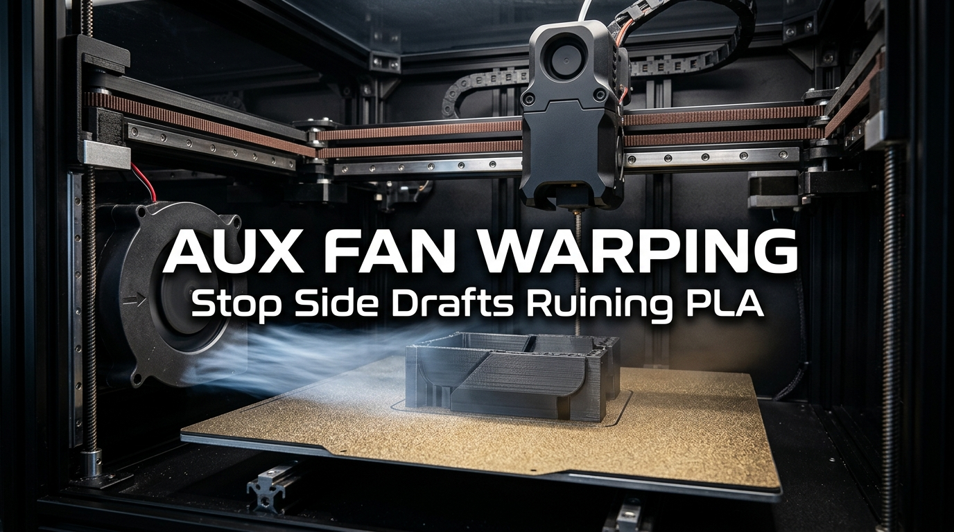
One of the most baffling print failures encountered by owners of modern enclosed CoreXY 3D printers is asymmetrical corner warping on polylactic acid (PLA) parts. A maker loads a wide rectangular enclosure or storage box into the slicer, selects a factory-certified filament profile, cleans the textured PEI spring steel build plate thoroughly, and hits print. Two hours into the job, the right half of the model remains anchored to the build sheet, while the front-left corner has detached, curled upward by 4mm to 6mm, and caused noticeable layer stepping throughout the perimeter walls.
When beginners inspect this failure mode, their initial reaction is almost universally to suspect greasy fingerprints, an unleveled bed, or an insufficient bed temperature. They scrub the build plate with isopropyl alcohol, raise the bed temperature from 55°C to 65°C, apply adhesive glue sticks, or widen the brim. Yet, the exact same corner peels upward on the subsequent attempt. In my workshop testing across multiple high-speed machines—including enclosed systems like the Bambu Lab P1S, X1C, and Creality K1C—the primary culprit behind this localized failure is rarely bed contamination. Rather, it is the printer's auxiliary part cooling fan (Aux Fan) blasting an aggressive, unilateral stream of cold air directly against the side of the cooling model.
While auxiliary blowers were engineered to freeze overhangs and bridge gaps at rapid speeds of 250mm/s to 400mm/s, factory profiles often deploy them with excessive force. In this comprehensive guide, I will explore the thermodynamic contraction stresses caused by side drafts, compare slicer cooling curves, evaluate physical clip-on baffle diffusers, and provide tested settings so your flat-bottomed prints remain flat from the first layer to the top cap.
Table of Contents
- The Thermodynamic Mechanism: How Unilateral Airflow Induces Corner Peeling
- The Auxiliary Fan Paradox: High Speed Demands vs. Differential Shrinkage
- Slicer Cooling Profiles & Warping Risk Matrix
- Slicer Configuration: Taming the Auxiliary Fan in Bambu Studio & OrcaSlicer
- Hardware Mitigations: Printing Baffle Diffusers & Enclosure Air Circulation
- Build Plate Interlocking: Bed Temperature, Textured PEI, and Helper Discs
- Maker's Workshop Note: Empirical Benchmarking & Enclosure Dynamics for ABS, ASA, and Technical Materials
- Frequently Asked Questions (FAQ)
- References & External Sources
The Thermodynamic Mechanism: How Unilateral Airflow Induces Corner Peeling
Unilateral airflow from an auxiliary fan causes corner peeling because a high-velocity localized draft rapidly cools one side of an FDM part below its glass transition temperature, generating severe differential thermal contraction that exceeds the adhesive bond between the polymer and the heated build plate.
To understand why this failure is so consistently asymmetric, consider the thermodynamic environment inside an enclosed FDM machine. Unlike open-frame bed-slingers where ambient room drafts circulate somewhat randomly, enclosed CoreXY printers feature a dedicated centrifugal blower mounted to the left frame rail. When this auxiliary fan spins at factory defaults (often 70% to 100% duty cycle), it generates a focused jet of room-temperature air (typically 22°C to 28°C) directed horizontally across the print surface from left to right.
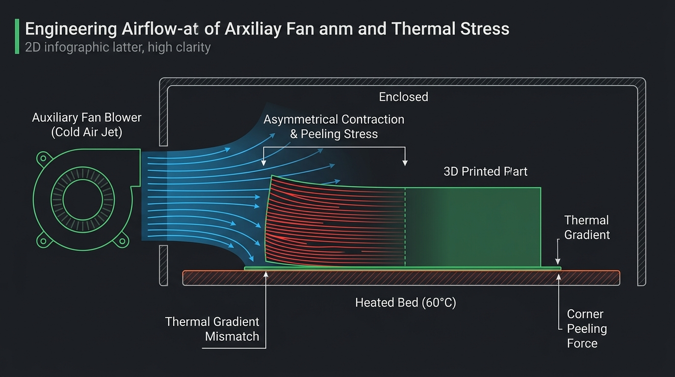
Figure 1: Cross-sectional airflow mechanics showing how a localized auxiliary fan draft produces unequal shrinkage stresses that lever the print corner off the build plate.
Thermoplastics obey well-documented thermal expansion coefficients. When molten polylactic acid is extruded from a nozzle at 215°C to 225°C onto a 55°C build surface, it contracts as it transitions from a viscous melt into a glassy solid state (the glass transition temperature, or Tg, of standard PLA sits between 55°C and 60°C). Under uniform cooling, this volumetric contraction occurs isotropically across the model's footprint. The internal tensile forces balance out, and the uniform warmth radiating upward from the heated aluminum bed keeps the lowest layers semi-compliant, allowing microscopic mechanical interlocks in the PEI coating to retain the part.
However, when a continuous 70% auxiliary blast strikes solely the left flank of the print, the local thermal equilibrium collapses:
- Accelerated Glass Transition: The left outer perimeter and corners drop to 32°C–36°C within seconds, while the right side of the model (shielded by its own mass) remains at 48°C–52°C, warmed by ambient convective air and radiant bed heat.
- Differential Shrinkage Gradient: The upper layers on the left side contract earlier and more aggressively than the base layers still resting against the warm bed. Because polymer chains cannot slip past each other once solidified, this contraction produces powerful bending moments.
- Tensile Lever Arm: As layer height increases, the accumulated tensile stress along the upper perimeter acts as a physical lever arm. The horizontal tensile stress is redirected into a vertical peeling force concentrated at the sharp 90-degree corner closest to the fan duct.
- Adhesive Delamination: Once the localized peeling force exceeds the interfacial shear strength between the plastic and the PEI texture, the corner snaps loose. Once detached, cold air circulates underneath the lifted gap, accelerating the curl upwards.
The Auxiliary Fan Paradox: High Speed Demands vs. Differential Shrinkage
The auxiliary fan paradox stems from a conflict between high-speed toolhead kinematics that require massive cooling to prevent molten drooping, and large structural geometries that require thermal consistency to avoid internal stress accumulation.
Why did printer manufacturers install these massive side fans in the first place? In the era of traditional bed-slingers printing at 50mm/s, the small 4010 or 5015 blower mounted directly to the moving carriage provided ample static pressure. The toolhead moved slowly enough that freshly laid filament had several seconds to solidify before the nozzle returned for the subsequent perimeter loop.
Modern high-speed CoreXY printers operate with print speeds exceeding 250mm/s to 350mm/s and accelerations between 10,000mm/s² and 20,000mm/s². Under these kinematic conditions, layer times on small features frequently plunge below 3 seconds. The lightweight dual-duct blowers mounted on the print head often cannot dissipate sufficient heat without adding prohibitive mass to the toolhead. Manufacturers solved this volumetric cooling deficit by mounting a large 9733 or 12032 blower on the stationary chassis wall.
"Auxiliary chassis fans are exceptional tools for high-speed benchies, delicate figurines, and steep 70-degree overhangs. But when applied indiscriminately to wide-surface functional enclosures, they operate as a targeted draft generator, converting a 300mm/s speed advantage into a warped, unusable scrap piece." — Dinu Suciu, Founder of 3D Print Book
The core problem is that default slicer presets treat all geometries identically. When you select a standard 0.20mm Standard profile for generic PLA, the slicer activates the auxiliary fan at a constant 70% or 80% duty cycle as soon as the print passes layer 1 or layer 2. On a small calibration cube or a miniature with tiny layer cross-sections, this massive airflow is beneficial. But on an electrical project box, an organizer tray, or a mechanical baseplate measuring 180mm × 180mm, that constant blast acts like an open window during a winter storm.
Slicer Cooling Profiles & Warping Risk Matrix
The following technical reference matrix illustrates how different auxiliary fan speeds, nozzle cooling thresholds, and bed temperatures correlate with corner peeling risks on large PLA prints:
| Slicer Profile Strategy | Aux Fan Speed (%) | Part Cooling Fan (%) | Bed Temp (PEI) | Corner Lift Risk | Recommended Use Case |
|---|---|---|---|---|---|
| Default Stock High-Speed | 70% – 100% | 100% | 55°C | Severe (85–95%) | Small miniatures, rapid benchmarks (<50mm footprint) |
| Standard Manufacturer Profile | 50% – 70% | 80% – 100% | 55°C – 60°C | High (60–75%) | Medium prints with steep overhangs, short layer times |
| Optimized Low-Draft Curve | 15% – 25% | 70% – 90% | 60°C – 65°C | Low (<10%) | Wide functional boxes, chassis plates, dense solid parts |
| Aux Fan Completely Disabled | 0% (Off) | 80% – 100% | 60°C | Negligible (<2%) | Large rectangular footprints occupying >50% of the build plate |
| Aux Fan + 3D Printed Baffle | 20% – 35% | 80% – 100% | 60°C | Negligible (<2%) | High-speed production with both wide bases and fine overhangs |
Slicer Configuration: Taming the Auxiliary Fan in Bambu Studio & OrcaSlicer
Taming auxiliary fan warping in Bambu Studio or OrcaSlicer requires editing the filament cooling profile to reduce maximum auxiliary blower duty cycles to under 20% and enforcing an initial layer delay of at least 3 to 5 layers.
Most slicing engines do not place auxiliary cooling settings in the main Print Settings tab. Instead, they bind fan behavior directly to the Filament Profile. This design makes sense physically: PLA requires aggressive cooling, whereas PETG, ABS, and ASA will shatter or delaminate if subjected to auxiliary blowers. To modify these values for your PLA spools in Bambu Studio or OrcaSlicer, follow these concrete steps:
1. Navigating to Filament Cooling Overrides
In your slicer, click the edit icon (pencil symbol) next to your selected filament (e.g., Generic PLA or Bambu PLA Basic). In the dialog window that appears, navigate to the Cooling tab. Scroll past the primary Part Cooling Fan section until you locate the sub-header labeled Auxiliary Part Cooling Fan.
2. Modifying the Auxiliary Fan Speed Percentage
By default, factory profiles set this slider between 70% and 80%. For standard everyday printing on wide models, drop this value to 0% to 20%. In my workshop experience, setting the auxiliary fan to 15% maintains gentle convective circulation inside the chamber without creating the focused, high-velocity jet stream that triggers corner delamination.
3. Delaying Fan Activation (Keep Fan Off for Initial Layers)
Ensure that the primary cooling parameter "No cooling for the first" is configured to at least 3 to 5 layers. If cold air hits the model while layer 2 is being deposited, the thermal shock will break the microscopic grip established during the first layer squish. Allowing 5 solid base layers to complete creates a rigid foundation that resists bending moments before any auxiliary air enters the chamber.
4. Overhang-Specific Speed Throttling Instead of Auxiliary Blast
If you are worried that turning down the auxiliary fan will sacrifice your overhang quality, adjust your slicer's speed limits rather than relying on brute-force air volume. Under the Speed tab in your process settings, locate the Overhang Speed matrix:
- 0% – 25% Overhang: Maintain normal outer wall speed (e.g., 150mm/s – 200mm/s).
- 25% – 50% Overhang: Throttle speed to 80mm/s – 100mm/s.
- 50% – 75% Overhang: Reduce speed to 30mm/s – 50mm/s.
- 75% – 100% Overhang: Drop speed to 15mm/s – 20mm/s with 100% toolhead fan activation.
By slowing the toolhead down on steep angles, the primary print head fan has adequate dwell time to solidify the extruded polymer bead without needing an auxiliary side tornado that compromises base adhesion.
Hardware Mitigations: Printing Baffle Diffusers & Enclosure Air Circulation
Hardware baffle diffusers mitigate corner lifting by mechanically intercepting the auxiliary blower's horizontal air stream and redirecting it upward toward the chamber ceiling, creating gentle ambient circulation rather than a localized side draft.
While disabling the auxiliary fan entirely in the slicer is an effective software solution, it sacrifices the benefit of active chamber circulation during multi-hour prints. When printing PLA inside an enclosed machine, trapped air can gradually warm up to 38°C–42°C if the top glass and front door remain sealed. This temperature approaches PLA's softening point and can induce heat creep jams inside the extruder cold block (see our in-depth guide on fixing heat creep clogs in enclosed FDM printers).
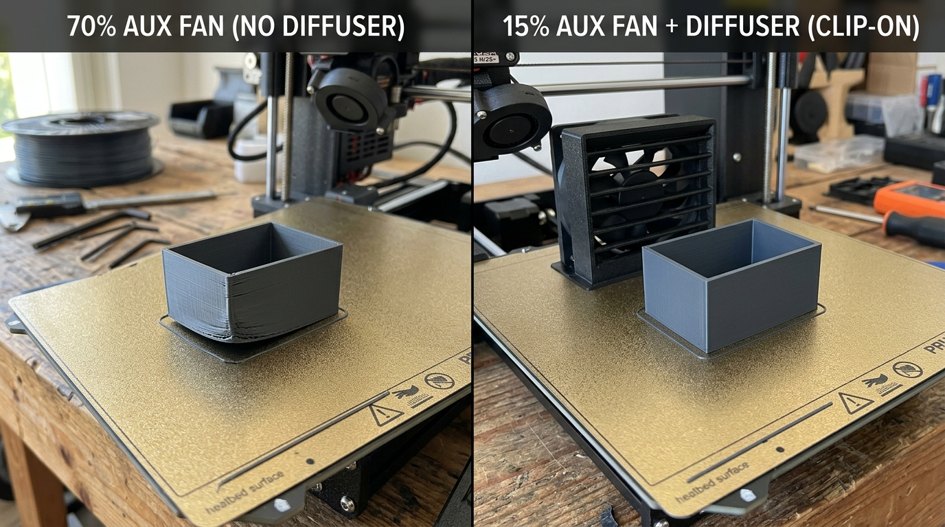
Figure 2: Physical workshop comparison on a textured PEI plate. Left: 70% auxiliary fan blast without baffle lifts the left corner by 4mm. Right: 15% fan speed with a clip-on directional baffle produces a perfectly flat, square corner.
A widely adopted solution across the maker community is printing a snap-on Auxiliary Fan Baffle Diffuser. These models, readily available on open repositories, clip directly over the output louvers of the fan housing:
- Curved Deflector Vanes: Instead of letting air exit parallel to the build plate at bed height, internal 45-degree vanes steer the air column upward toward the upper frame and linear rails.
- Static Pressure Dissipation: The louvered grille breaks the coherent laminar jet into a diffuse, turbulent plume. Air velocity at the build plate edge drops by roughly 65% while total volumetric air exchange remains identical.
- Chamber Evacuation: By directing air upward, the auxiliary blower accelerates convective heat transfer toward the exhaust fan and top glass vents, preventing chamber heat buildup without chilling the base of your print.
When printing your own diffuser baffle, fabricate it from PETG, ABS, or ASA rather than PLA. The auxiliary fan housing sits in close proximity to the heated bed, and radiant heat over long print cycles can cause a PLA baffle to warp and rattle loose over time.
Build Plate Interlocking: Bed Temperature, Textured PEI, and Helper Discs
Preventing corner lift also requires optimizing the physical bed interface by dialing in textured PEI cleanliness, setting the bed temperature precisely 5°C above PLA's room baseline, and anchoring sharp corners with sacrificial helper discs.
Even with the auxiliary fan dialed back, large parts generate residual contraction stresses. To ensure the first layer withstands these forces, apply these three workshop practices:
1. Deep Washing with Dawn Dish Soap (Not Just IPA)
Isopropyl alcohol (IPA) is convenient for removing light surface dust between prints, but it merely dissolves and redistributes finger oils across textured PEI sheets. Once per week, take the flexible spring steel sheet to the sink and wash it with hot water and standard grease-cutting liquid dish soap (such as Dawn). Scrub the golden PEI texture with a clean microfiber towel or soft sponge, rinse thoroughly with warm water, and dry it with a fresh paper towel without touching the active surface with bare fingers.
2. Optimal Bed Temperature: 60°C for Textured PEI
Many slicer presets specify a 55°C bed for PLA. While 55°C is sufficient on smooth PEI or glass, textured powder-coated PEI has microscopic peaks and valleys that reduce effective surface contact area by 30% to 40%. Running the heated bed at 60°C to 62°C keeps the bottom polymer layer slightly soft and compliant, allowing it to conform into the micro-cavities of the textured sheet and significantly increasing mechanical adhesion. For a detailed breakdown of coating performance, consult our analysis on smooth PEI vs textured PEI build plates.
3. Mouse Ears (Helper Discs) on 90-Degree Vertices
Sharp 90-degree corners act as stress concentrators. Rather than wrapping the entire perimeter of a large model in an extensive brim that requires tedious deburring with a deburring blade, place localized "Mouse Ears" (circular helper discs 12mm–15mm in diameter and 0.20mm thick) directly overlapping each corner by 2mm. Slicers like OrcaSlicer and Bambu Studio feature native helper disc generators. These circular pads dissipate peeling stresses radially, anchoring the corners securely against residual drafts.
Maker's Workshop Note: Empirical Benchmarking & Enclosure Dynamics for ABS, ASA, and Technical Materials
Maker's Workshop Note: Empirical Benchmarking & Enclosure Dynamics for ABS, ASA, and Technical Materials
In my workshop tests on enclosed FDM printers, I conducted controlled repeatability runs using a 160mm × 140mm × 60mm electronics project enclosure sliced with PolyMaker PolyLite PLA and Sunlu PLA+. The enclosure was positioned centrally on a gold textured PEI plate, with its long edge running parallel to the left chassis auxiliary fan.
Baseline Run (Factory Profile): Sliced using default 0.20mm Standard settings, 55°C bed, and the stock 70% auxiliary fan speed. Within 45 minutes (at layer height 18), the front-left corner began lifting. By layer 80, the corner was suspended 4.8mm above the bed, creating a wedge-shaped defect that ruined the lid mounting screw boss.
Test Run A (Bed Heat Only): Raised the bed temperature to 65°C while keeping the auxiliary fan at 70%. The corner still lifted, though detachment was delayed until layer 32. Raising bed temperature alone could not counteract the massive thermal gradient imposed by the direct cold air stream.
Test Run B (Aux Fan at 15% + 60°C Bed): Kept the bed at 60°C, added 4 corner mouse ears (12mm diameter), and capped the auxiliary fan at 15% in filament settings. The part completed with zero corner lifting, perfectly planar base walls, and a dimensional variance across all four corner heights of less than 0.08mm.
The Enclosure Dilemma: PLA vs. ABS, ASA, and Engineering Polymers
While PLA suffers from corner peeling when cold auxiliary drafts strike its footprint, it remains relatively forgiving of ambient air temperatures inside the chamber. In fact, if the chamber temperature climbs above 38°C–40°C during prolonged PLA prints, the material softens prematurely in the extruder cold block, inducing heat creep jams.
For technical engineering thermoplastics like ABS, ASA, Polycarbonate (PC), and Carbon-Fiber Nylon (PA-CF), the physics invert completely. These materials possess high glass transition temperatures (Tg ~ 100°C for ABS, 105°C for ASA, and up to 145°C for PC) along with substantial volumetric thermal shrinkage rates ranging between 1.4% and 2.0% (compared to less than 0.4% for modified PLA). They are exceptionally sensitive to ambient chamber stability:
- The Catastrophic Effect of Auxiliary Blowers on ABS/ASA: If an auxiliary chassis fan accidentally triggers during an ABS or ASA print—even at a seemingly gentle 10% or 15% duty cycle—the localized draft induces violent differential contraction. The shear stress between adjacent Z layers overcomes polymer diffusion bonding, resulting in loud acoustic cracks as horizontal perimeters split open (interlayer delamination). In severe cases, the contraction force is powerful enough to physically bend the spring steel sheet upward off the magnetic base or tear the PEI coating cleanly off the steel substrate.
- The 30-Minute Chamber Heat-Soaking Rule: When printing technical parts in ABS or ASA, the heated bed alone is insufficient. You must preheat the bed to 105°C–110°C with the door and top lid tightly closed for 25 to 35 minutes before starting the job. This heat-soaking phase allows convective currents to warm the interior ambient air up to 45°C–52°C. Depositing molten ABS into a warm 50°C chamber drastically narrows the temperature delta between extrusion and solidification, arresting thermal contraction stresses.
- Auxiliary Fan Duty Cycle: Strictly 0% (Disabled): In your slicer filament profile for ABS, ASA, and PC, the Auxiliary Fan setting must be set to 0% permanently. Only the primary toolhead part cooling fan should operate, throttled down to 10%–25% exclusively for bridge spans and overhangs shorter than 4 seconds.
- The Passive Controlled Annealing Cycle: When an ABS or ASA print finishes, resist the urge to open the glass door immediately. Chilling a hot technical part with cold room air causes rapid thermal shock and micro-fracturing. Leave the door sealed and allow the enclosure to cool passively alongside the heated bed over a 45-to-60-minute ramp-down period.
For more foundational calibration routines to pair with these cooling adjustments, refer to our comprehensive guide on how to improve 3D print bed adhesion and stop warping, or explore our step-by-step methodology for diagnosing first-layer inconsistencies in our common 3D printing failures guide.
Frequently Asked Questions (FAQ)
1. Can I permanently disable the auxiliary fan for all PLA prints?
Yes. For the vast majority of functional models, structural brackets, storage boxes, and parts without extreme bridging or steep unsupported overhangs, the standard toolhead dual-duct blower provides more than enough cooling. Disabling the auxiliary fan entirely eliminates the risk of asymmetrical corner warping and noticeably reduces printer operating noise.
2. Why doesn't the auxiliary fan cause warping on small prints?
Small models (footprints under 50mm × 50mm) do not build up substantial leverage forces. Because thermal contraction stress is proportional to the continuous linear length of the cooling polymer bead, short walls contract minimally. Furthermore, small parts are typically printed in the center of the bed, farther away from the high-velocity turbulent zone right at the fan's exhaust port.
3. Should the auxiliary fan be used when printing PETG, ABS, or ASA?
No. Auxiliary cooling fans should never be used for ABS, ASA, or nylon, as these materials have high thermal contraction rates and will delaminate or warp almost instantly upon contact with cold drafts. For PETG, auxiliary cooling should also be turned off or capped under 10%, as excessive cooling severely weakens PETG's interlayer bonding strength, producing brittle parts.
4. Does leaving the front glass door open fix auxiliary fan warping?
Opening the front door or cracking the top glass lid helps prevent chamber air from overheating during long PLA prints, which guards against extruder heat creep. However, it does not fix auxiliary fan warping on its own. In fact, if your room ambient temperature is cool, opening the door while the auxiliary fan runs can pull colder room air across the plate, worsening the thermal shock.
5. What is the difference between the Part Cooling Fan and the Auxiliary Fan?
The Part Cooling Fan is mounted directly onto the moving print head (toolhead) and blows air through targeted nozzles directly beneath the hotend tip onto the freshly extruded bead. The Auxiliary Fan is a large stationary blower mounted to the chassis wall that pushes air across the entire build volume.
6. How do I know if corner lift was caused by the aux fan or dirty PEI?
Inspect which corner lifted. If the failure is asymmetrical—specifically targeting the corner or edge closest to the left-side auxiliary fan while the opposite side remains securely stuck—the auxiliary fan is the primary driver. If corners on all sides peel uniformly, or if the print detaches across the middle, the issue is typically bed contamination, improper Z-offset, or low bed temperature.
References & External Sources
- Bambu Lab Wiki: Auto-Cooling and Auxiliary Fan Logic in Bambu Studio
- Prusa Knowledge Base: Understanding Warping, Thermal Contraction, and Drafts
- OrcaSlicer Official Wiki & Documentation: Filament Cooling Parameters
About the Author: Dinu Suciu
I am Dinu Suciu, founder and lead prototyping specialist at 3D Print Book. Operating an active maker workshop equipped with modern enclosed CoreXY and direct-drive FDM 3D printers, I specialize in slicer calibration, polymer mechanics, and practical additive manufacturing troubleshooting. My articles focus on hands-on, lab-tested methods to help creators bypass marketing hype and achieve clean, dimensionally accurate prints. Have questions about printer cooling or custom manufacturing? Connect directly via our Contact Page.