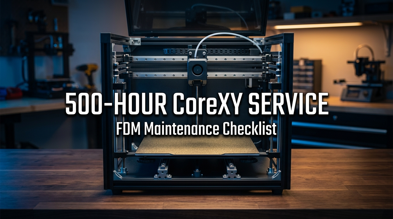
Modern enclosed CoreXY 3D printers often feel like hands-off kitchen appliances during their first weeks of operation. You unpack the chassis, run the automated self-check, and watch toolheads rip across the build plate at 500 mm/s with 20,000 mm/s² acceleration. Yet underneath that polished exterior, violent kinetic energy takes a continuous mechanical toll.
Every rapid direction change stretches fiberglass reinforcement cords inside your timing belts. Every high-speed perimeter sheds microscopic plastic particles between dual-drive gear teeth, and every high-temperature chamber heat soak slowly cooks factory grease into sticky sludge along linear rails and Z-axis lead screws. By the time an odometer hits roughly 500 printing hours, minor dimensional drift, subtle surface ringing, and intermittent extruder slips start to creep into your parts.
Performing a dedicated 500-hour service routine restores factory tolerances, keeps motion smooth, and stops expensive catastrophic hardware breakdowns before they ruin a multi-day prototype. In this hands-on workshop guide, we walk through the exact inspection points, cleaning solvents, lubrication protocols, and belt frequency checks required to maintain enclosed CoreXY hardware at peak reliability.
Table of Contents
- Why High-Speed CoreXY Printers Need 500-Hour Service
- Cleaning Carbon Rods vs Lubricating MGN12 Steel Rails
- Checking Belt Tension, Idler Bearings, and Pulleys
- Brushing Extruder Drive Gears and Inspecting Hotend Cables
- Z-Axis Lead Screw Cleaning and Bed Tramming Alignment
- The 500-Hour CoreXY Maintenance Matrix
- Maker Workshop Observations: Real Wear Patterns After 500 Hours
- Post-Service Calibration: Input Shaping and Flow Verification
- Frequently Asked Questions (FAQ)
- References & External Sources
Why High-Speed CoreXY Printers Need 500-Hour Service
High-speed CoreXY 3D printers require structured 500-hour service because long, crossed timing belts stretch under extreme acceleration forces, dry friction mounts shed microscopic debris, and high chamber temperatures degrade grease inside carriage bearings.
Unlike traditional Cartesian bed-slingers where the heavy print bed moves back and forth along the Y-axis at modest accelerations (typically 1,000 to 3,000 mm/s²), a CoreXY gantry uses two stationary stepper motors that coordinate motion across a unified pair of interlocking belts. To move the toolhead diagonally, both motors spin simultaneously; to move along a single axis, one motor spins clockwise while the other spins counterclockwise. This interconnected kinematic system delivers blistering travel speeds, but it also means that any friction, looseness, or wear in one corner immediately distorts motion across the entire print plane.
At 500 operating hours, an active printer has completed roughly 1.8 million seconds of motion. Under typical print speeds of 200 to 400 mm/s, the printhead has traveled hundreds of kilometers. During that operational lifespan, three distinct degradation mechanisms occur simultaneously:
- Kinetic Belt Elongation: The continuous tension cycles on 2GT timing belts gradually loosen the belt weave, leading to unequal tension between the A and B loops. This imbalance turns circular holes into subtle ovals and introduces ghosting along 45-degree walls.
- Contaminant Accumulation in Motion Components: As the cooling fan draws room air across the toolhead, airborne dust mixes with fine filament particles shed by the extruder. When sucked into linear rail carriages or deposited onto dry carbon rods, this gritty paste increases drag and triggers stepper skip errors.
- Volatilization of Factory Lubricants: Enclosed printing chambers often maintain internal temperatures between 45°C and 60°C when running ABS, ASA, or PETG. Extended exposure to these temperatures evaporates volatile oils from standard mineral greases, leaving behind a waxy, sticky residue that binds linear bearings.
Treating routine maintenance as an afterthought usually ends in emergency repairs—snapped belts, gouged guide rods, or stripped extruder gears during critical production runs. Taking two hours to execute a structured 500-hour service overhaul preserves machine precision and extends component lifespans by thousands of hours.
Cleaning Carbon Rods vs Lubricating MGN12 Steel Rails
Carbon fiber guide rods must be kept completely dry and cleaned exclusively with 99% isopropyl alcohol, whereas steel linear rails require thorough solvent degreasing followed by synthetic NLGI 1 or 2 lithium grease application.
One of the most widespread and expensive mistakes in high-speed 3D printer maintenance is applying liquid oil or grease to carbon fiber rods. Carbon fiber X-axis guide assemblies—popularized by modern enclosed machines like the Bambu Lab X1 and P1 series—rely on self-lubricating sintered bronze, graphite, or polymer bushings. The microscopic graphite particles embedded in the bushing material create a natural low-friction interface as they glide along the polished carbon weave.
When liquid oil or aerosol lubricants (such as WD-40 or silicone spray) are applied to carbon rods, the fluid does not reduce friction. Instead, it forms a sticky wet film that captures airborne filament dust and carbon fibers. Within dozens of hours, this slurry packs into the bushings, increases sliding resistance by more than 300%, and causes layer shifts that trigger firmware motor overload warnings.
Step-by-Step Carbon Rod Cleaning Protocol
- Power Down and Disconnect: Turn off the printer power switch and unplug the AC power cord to prevent accidental toolhead movement or short circuits.
- Dampen a Lint-Free Wipe: Soak a clean microfiber cloth or lint-free Kimwipe in 99% technical-grade isopropyl alcohol (IPA). Avoid standard 70% drugstore rubbing alcohol, which contains 30% water and cosmetic oils that leave streaky film residues.
- Wipe the Full Rod Span: Firmly wrap the dampened cloth around each carbon rod and slide it back and forth from the far left limit to the far right limit. You will notice dark black residue on the cloth; this is a normal mixture of ambient dust and shedding graphite binder.
- Cycle the Carriage: Manually slide the toolhead carriage back and forth across the gantry by hand to dislodge any debris trapped inside the bushing housing, then wipe the exposed rod surface again with a fresh, clean section of the cloth.
- Allow Full Solvent Evaporation: Wait 5 to 10 minutes for the alcohol to completely evaporate. The rods should look uniformly matte black and feel completely smooth and dry to the touch.
Step-by-Step Steel Linear Rail (MGN9 / MGN12) Servicing
If your CoreXY printer features stainless steel linear guide rails on the X or Y axes (such as a Creality K1, K1 Max, K2 Plus, Voron 2.4, or RatRig), the maintenance requirement is the exact opposite of carbon rods: steel rails must never run dry. The recirculating chrome steel ball bearings inside the carriage block require an unbroken hydrodynamic lubricating film to prevent metal-on-metal micro-galling.
For detailed technical background on lubricant viscosities, review our dedicated guide on synthetic grease vs lightweight oil for MGN12 rails. In our workshop 500-hour overhaul, we use the following procedure:
- Strip Old Contaminated Grease: Spray a small amount of IPA onto a clean lint-free cloth and wipe away old, blackened grease along the top, bottom, and ball-groove tracks of each steel rail. Slide the carriage to one end, clean the newly exposed metal, and repeat on the opposite side.
- Inspect Ball Grooves for Pitting: Run a fingernail along the precision ground ball tracks. If you detect notches, rough grooving, or rust discoloration, the carriage block or rail has suffered abrasive wear and must be replaced.
- Inject Fresh Synthetic Grease: Using a grease syringe fitted with a blunt dispensing needle, inject an NLGI Grade 1 or Grade 2 synthetic grease containing PTFE (such as Super Lube 21030 or Mobilux EP 1) directly into the carriage grease port. If no grease port is accessible, apply a neat bead of grease along the ball retention grooves on both sides of the rail.
- Distribute the Lubricant: Slowly move the carriage through its entire travel stroke 15 to 20 times. This forces the internal recirculating balls to roll through the grease reservoir and coat all internal contact surfaces. Wipe away excess grease that gathers at the rubber end-wiper seals to prevent it from dripping onto your print bed.
Checking Belt Tension, Idler Bearings, and Pulleys
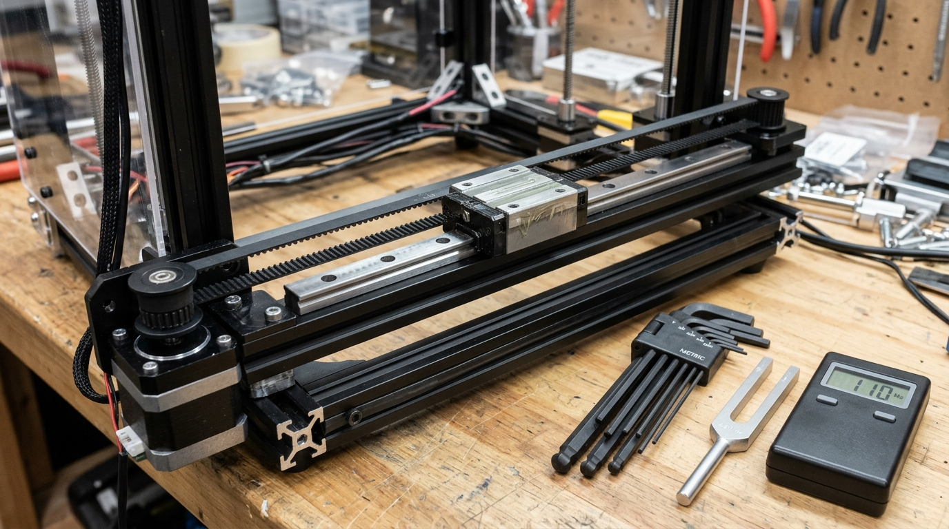
CoreXY timing belts must be inspected for frayed teeth, equalized between the A and B loops using audio frequency analysis (typically 110 to 140 Hz over a 150 mm span), and checked for pulley bearing runout.
Timing belt tension is the single most critical mechanical factor governing geometric dimensional accuracy and surface finish on CoreXY machines. Because the A and B belts work against each other to position the toolhead, a tension discrepancy between the two loops skews the gantry squareness. When one belt is tighter than the other, 90-degree corners print as parallelogram angles, circles turn into ellipses, and high-frequency vibrations produce visible ghosting.
Visual Belt Inspection Checkpoints
Before adjusting tension screws, carefully inspect the entire belt perimeter with a flashlight while slowly rotating the gantry:
- Tooth Shearing and Flaking: Look for missing neoprene teeth or white rubber powder gathering on idler brackets. Powder accumulation indicates that a belt is rubbing against pulley flanges due to tilted idler shafts.
- Cord Fraying along Edges: Check the lateral edges of the 6 mm 2GT belts. If fiberglass tensile cords are poking out or unraveling, the belt has suffered edge friction and has lost structural stiffness. Replace frayed belts immediately.
- Backside Glazing: Smooth idler pulleys ride against the toothless back of the belt. If the backside shows shiny, hardened, or cracked rubber, heat and over-tension have caused premature dry rot.
Acoustic Frequency Tuning Protocol
While spring gauges provide a rough estimation, professional makers and print farm operators tune CoreXY belts using acoustic frequency measurement. Just like a guitar string, a belt stretched across a fixed span resonates at a frequency proportional to its tension.
To measure belt frequency accurately, park the toolhead at the exact center front of the build volume so both belt spans have identical free lengths (typically 150 mm on standard 250 mm to 300 mm frames). Open an acoustic frequency analyzer app (such as Spectroid on Android, GuitarTuna, or Gates Carbon Drive Mobile) on your smartphone and hold the microphone roughly 10 mm away from the belt span.
Pluck the belt cleanly with a guitar pick or hex key. In my workshop tests, standard 6 mm fiberglass-reinforced Gates 2GT belts on modern CoreXY printers achieve optimal damping and dimensional stiffness when tuned to 110 Hz – 130 Hz across a 150 mm span. Most importantly, both the A and B belts must match within ±2 Hz of each other. If one belt reads 135 Hz while the other reads 115 Hz, loosen the tensioner on the tighter belt and tighten the looser one until the frequencies converge.
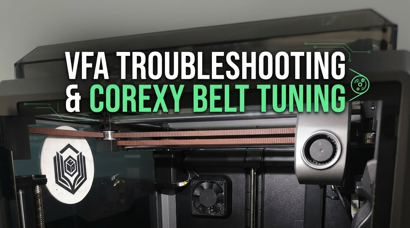
For in-depth troubleshooting of vibrational surface patterns caused by incorrect belt resonance, refer to our complete guide on diagnosing Vertical Fine Artifacts (VFA) and belt frequency tuning.
Inspecting Idler Pulleys and Stepper Shafts
While the belts are relaxed during adjustment, spin every idler pulley and toothed drive pulley by hand. Pulleys should rotate with zero resistance, zero gritty clicking, and zero detectable lateral play. In high-speed printers running 20,000 mm/s² acceleration, miniature 623zz and 684zz flanged idler bearings undergo massive radial shock loads. If an idler wobbles or makes a scraping noise, its internal ball cage is worn. Replacing a $2 bearing saves you from snapped belts and ruined prints down the line.
Brushing Extruder Drive Gears and Inspecting Hotend Cables
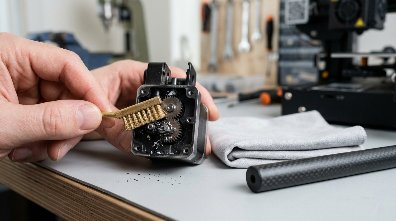
Dual-drive extruder gears accumulate packed filament dust inside their hobbed drive teeth, reducing grip tension and causing intermittent under-extrusion that can only be cured by mechanical brushing.
High-speed direct-drive toolheads utilize hardened steel dual-drive gears to push filament through high-flow melt zones. Every time a print performs aggressive retractions, pressure advance micro-steps, or handles abrasive filaments like carbon fiber and glass-filled blends, tiny filament shavings grind off the spool. Over 500 hours of extrusion, this plastic dust packs tightly into the concave root of the drive teeth.
Once gear teeth are clogged with plastic debris, their effective tooth depth shrinks. The extruder can no longer bite firmly into the filament core, leading to slipping, false filament tangle sensor triggers, and sudden under-extrusion on fast infill passes.
Extruder Gear Cleaning Steps
- Release Idler Tension: Open the extruder tension arm or loosen the manual tension screw on the toolhead housing.
- Inspect Teeth with Light: Shine an inspection light into the filament path. You will clearly see white, grey, or colored plastic dust packed between the hardened teeth.
- Scrub with a Brass Wire Brush: Use a fine, stiff brass wire brush to sweep debris out of the tooth valleys. Rotate the manual drive wheel or use the printer display's extruder feed command to rotate the gears 360 degrees until all teeth are shiny steel. Avoid steel wire brushes on nickel-plated or standard steel gears to prevent gouging.
- Blow Out the Cavity: Use a burst of compressed air or a manual air bulb to blow out loose filament crumbs from the extruder gearbox. Avoid blowing debris into the hotend heatsink throat.
- Check Drive Shaft Bearings: Lightly lubricate needle bearings or drive gear pivot pins with a single micro-drop of synthetic grease, taking extreme care not to get any lubricant on the hobbed filament contact teeth.
Hotend Cable Harness and Thermistor Strain Relief
The rapid whip-crack motion of CoreXY gantries places extreme mechanical fatigue on the wiring harness connecting the mainboard to the moving toolhead. During your 500-hour service inspection, examine the toolhead umbilical cable:
- Look for Pinch Points: Check where the cable bundle enters the toolhead clamp and where it mounts to the gantry drag chain or flexible umbilical spine. If insulation shows crimping, thinning, or exposed copper braiding, repair the sleeve immediately.
- Inspect Thermistor & Heater Connectors: High thermal cycling can loosen JST-GH or Molex Micro-Fit connectors on the toolhead breakout board. Gently wiggle each connector while monitoring live temperature readings on the display. If the nozzle temperature spikes or fluctuates erratically, re-crimp or replace the thermistor harness.
- Check PTFE Guide Tube Wear: Examine the reverse Bowden PTFE tube where filament enters the top of the toolhead. Rigid abrasive filaments (especially PA-CF and PET-CF) slowly carve a groove into the curved inner wall of the PTFE tube. If you see deep grooves or flat spots, trim 20 mm off the end or swap in fresh Capricorn high-lubricity tubing to reduce feed friction.
Z-Axis Lead Screw Cleaning and Bed Tramming Alignment
Z-axis lead screws accumulate fallen plastic crumbs and oxidized black grease, causing vertical layer height banding unless cleaned with solvent and re-lubricated with non-attracting synthetic PTFE grease.
While the X and Y axes handle rapid horizontal movements, the Z-axis is responsible for the absolute vertical consistency of every layer. Most enclosed CoreXY printers rely on two or three synchronized T8 lead screws driven by a continuous loop timing belt or independent stepper motors. Because lead screws sit directly beside the heated print bed, they operate in a challenging environment: hot ambient air, falling plastic purge fragments, and sticky filament vapors that settle onto greasy surfaces.
Over 500 hours, mineral grease on lead screws oxidizes into black sludge. When the brass or POM anti-backlash nut rides over trapped grit, it binds slightly, causing fractional Z-height discrepancies that show up as visible horizontal layer lines across the outer walls of your prints.
Z-Axis Maintenance Procedure
- Lower the Bed Assembly: Move the heated bed to the bottom limit of its travel stroke using the printer control screen.
- Degrease the Screw Threads: Wrap a microfiber cloth soaked in 99% IPA around each lead screw and rotate the screw manually or command the bed upward to wipe away all contaminated black lubricant from top to bottom. Use an old soft toothbrush dipped in IPA to scrub stubborn grime out of the thread roots.
- Inspect POM Anti-Backlash Nuts: Check the plastic or brass nut securing the bed frame to the screw. Gently lift the bed frame with your hands; if you feel vertical slop or play before the screw resists, the anti-backlash spring has weakened or the nut threads have worn out.
- Apply Fresh Lubricant: Apply a light, even line of synthetic PTFE grease along the upper half of each screw. Command the bed to travel down and up through its full stroke three times to distribute the grease across the thread contact zones. Wipe off excess globbing at the bottom of the screw to keep your workshop tidy.
- Check Z-Belt Synchronization: If your machine uses a bottom loop belt connecting multiple Z-screws (such as a Creality K1 or Voron Trident), check the belt tension and verify that the bed sits mechanically level relative to the top gantry frame before relying on auto-bed leveling mesh compensation.
The 500-Hour CoreXY Maintenance Matrix
To help you organize your workshop maintenance tasks systematically, the following technical comparison matrix outlines the recommended service intervals, cleaning agents, wear symptoms, and corrective actions for each CoreXY subsystem:
| Subsystem / Hardware Component | Inspection Frequency | Primary Wear Symptom | Service & Cleaning Action | Recommended Lubricant / Tool |
|---|---|---|---|---|
| Carbon Fiber Guide Rods (X-Axis) | Every 250–500 Hours | Layer shifts, grinding noise, motor load warnings | Wipe clean with lint-free microfiber cloth; do not lubricate | 99% Isopropyl Alcohol (IPA); strictly NO oil/grease |
| Stainless Steel Linear Rails (MGN9 / MGN12) | Every 300–500 Hours | VFA ripples, dry scratching sound, carriage play | Degrease ball grooves; inject fresh synthetic grease via port | NLGI 1 or 2 Synthetic PTFE Grease (Super Lube 21030) |
| 2GT Timing Belts (CoreXY A/B Loops) | Every 250–500 Hours | Ghosting, oval circles, edge fraying, loose frequency | Measure acoustic resonance (110–130 Hz); equalize loops | Spectroid App, guitar pick, 2.5 mm hex wrench |
| Flanged Idler Bearings & Pulleys | Every 500 Hours | Belt tracking rub, high-pitch squeak, bearing wobble | Check radial play by hand; replace worn 623zz/684zz bearings | Replacement ABEC-5 bearings, fine tweezers |
| Dual-Drive Hardened Extruder Gears | Every 250–500 Hours | Under-extrusion on infill, filament grinding, clicking | Open idler latch; brush plastic dust out of tooth valleys | Soft brass wire brush, compressed air bulb |
| Z-Axis T8 Lead Screws & POM Nuts | Every 500 Hours | Z-banding lines, sticky travel, vertical backlash | Strip old sludge with IPA; apply fresh synthetic grease | NLGI 2 PTFE Synthetic Grease, soft nylon brush |
| Toolhead Wiring Harness & Umbilical | Every 500 Hours | Erratic nozzle temp readouts, heater fault error | Inspect cable bend radius, re-seat loose JST connectors | Multimeter, zip-ties, braided cable sleeve |
Stock Up on Belts, Toolhead Spares & Workshop Gear
Keeping fresh Gates 2GT belts, hardened nozzles, and synthetic lubricants on your workshop shelf prevents unexpected downtime during high-volume print runs. Browse our curated 3D Printing Deals & Coupons page for verified discounts on CoreXY hardware, replacement spares, and active filament dryboxes.
Maker Workshop Observations: Real Wear Patterns After 500 Hours
Maker's Workshop Note: Lessons From 500 Hours on My Enclosed Printers
In my workshop tests across several high-speed enclosed FDM printers, I found that hardware failures rarely happen suddenly without warning. Instead, machines drop subtle hints across dozens of operating hours before an outright failure occurs.
The Early Warning Sign Most Makers Miss: When checking belt tension after hundreds of hours of high-speed printing, I tested the resonant frequencies across multiple chassis. In almost every case, the B belt had slackened roughly 15 to 20 Hz more than the A belt. This subtle divergence does not trigger immediate print failures; rather, it introduces a faint diagonal ghosting pattern that only becomes obvious under harsh raking light. Taking five minutes to bring both belts back to matching tension restored razor-sharp 90-degree corners instantly.
Extruder Gear Debris Accumulation: When printing high-speed technical parts with fiber-reinforced filaments like PETG-CF, I noticed that microscopic carbon fibers mix with ambient moisture to create an abrasive cake in the extruder tooth roots. After cleaning my Creality extruder gears with a brass brush during a 500-hour service overhaul, extrusion consistency improved dramatically, and my volumetric flow rates jumped back up to factory maximums. Skipping this step often causes makers to blame wet filament or worn nozzles when the actual culprit is simply a dirty drive gear slipping under backpressure.
Post-Service Calibration: Input Shaping and Flow Verification
After completing mechanical maintenance, running automated resonance sweeps and flow rate calibrations is essential to update firmware compensation tables for freshly tensioned belts and cleaned rails.
Every mechanical change you make during a service overhaul slightly alters the natural resonant frequency of the motion system. Tightening belts shifts the resonance peak higher up the frequency spectrum, while cleaning and lubricating linear rails reduces viscous damping. If you resume printing without re-calibrating your firmware's resonance compensation (Input Shaping), your printer will apply vibration-canceling algorithms configured for loose, dirty belts, which can actually worsen surface artifacts.
Post-Maintenance Calibration Protocol
- Run Automated Input Shaping (Resonance Testing): On Klipper-based printers equipped with an onboard ADXL345 accelerometer (such as the Creality K1 series or custom Voron builds), run the resonance testing routine:
Review the generated resonance graph. The frequency peaks should be sharp and distinct. Note the suggested shaper (e.g., MZV or EI) and max recommended acceleration, then save the new parameters to your firmware configuration.TEST_RESONANCES AXIS=X TEST_RESONANCES AXIS=Y - Re-Run Auto Bed Leveling (Bed Mesh): Because adjusting belt tension and cleaning Z-axis lead screws can slightly shift the bed frame geometry, run a full bed mesh probe at operational chamber temperatures (e.g., 60°C bed temperature). Verify that the total mesh variance stays below 0.15 mm across the entire build area.
- Calibrate Pressure Advance & Flow Rate: With clean extruder gears gripping filament with full tooth engagement, print a quick pressure advance line or tower test in OrcaSlicer. Freshly cleaned gears often deliver slightly higher extrusion volume per motor step, allowing you to fine-tune your extrusion multiplier for clean top surface layers.
Frequently Asked Questions (FAQ)
1. How often should I perform maintenance on a CoreXY 3D printer?
Light preventative maintenance (wiping down the build plate with IPA and clearing purge chute debris) should be done before every print. Intermediate checks (checking belt tension and inspecting nozzle wear) are recommended every 200 to 250 hours. A comprehensive mechanical overhaul covering lead screw degreasing, rail lubrication, extruder brushing, and input shaper re-calibration should be performed every 500 operating hours.
2. Can I use WD-40 or 3-in-1 oil to lubricate my printer's linear rails?
No. Standard multi-purpose WD-40 is a solvent and water displacer, not a long-term lubricant; it will dissolve factory grease and leave rails vulnerable to corrosion. Lightweight 3-in-1 mineral oils are too thin for high-speed linear carriages, causing the oil to fling off onto the bed during high acceleration passes. Use high-performance synthetic lithium grease containing PTFE (NLGI Grade 1 or 2) for steel linear rails.
3. Why shouldn't I lubricate carbon fiber rods?
Carbon fiber rods utilize self-lubricating dry polymer or graphite bushings. Applying liquid oil or grease to carbon rods creates a sticky film that attracts filament dust and airborne debris. This abrasive slurry packs inside the bushing clearances, causing friction spikes, motor stalls, and irreversible rod wear. Carbon rods must always be cleaned dry with 99% isopropyl alcohol.
4. What is the ideal belt tension for a CoreXY printer?
On typical desktop CoreXY printers using 6 mm 2GT belts over a 150 mm free span, the ideal acoustic frequency is between 110 Hz and 130 Hz. Most importantly, both the A and B belt loops must be balanced within ±2 Hz of each other to maintain square gantry geometry and prevent diagonal skew.
5. How do I know when my extruder gears need cleaning?
Common symptoms of clogged extruder drive gears include intermittent clicking or ticking noises during rapid infill printing, mysterious under-extrusion on long perimeters, and filament slipping when feeding through a hot nozzle. If you inspect the drive teeth with a flashlight and see colored plastic dust packed in the valleys, clean them with a stiff brass wire brush.
Related Guides & Next Steps
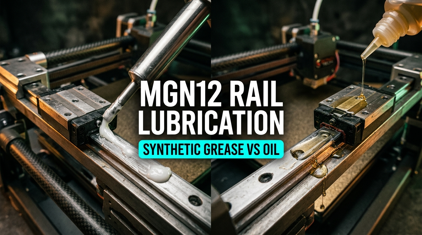
MGN12 Linear Rail Lubrication: Synthetic Grease vs Oil
Learn why light machine oils fail on high-acceleration MGN12 linear rails, how NLGI 1 and 2 synthetic greases protect bearings, and how to flush factory oil.
Best FDM 3D Printers 2026: Top Picks & Buyer's Guide
Choosing the right FDM 3D printer in 2026 can be overwhelming due to rapid technological shifts like high-speed CoreXY systems and multi-color printing. This guide highlights the best models.
References & External Sources
- Bambu Lab Official Wiki: Basic Maintenance Schedule & Carbon Rod Cleaning Guide
- Voron Design Documentation: CoreXY Mechanical Tuning, Belt Tension & Startup Checks
- Klipper Official Documentation: Measuring Resonances, Accelerometer Calibration & Input Shaping
- Prusa Knowledge Base: Regular Maintenance & Smooth Rod/Bearing Care
About the Author: Dinu Suciu
I am Dinu Suciu, founder and prototyping specialist at 3D Print Book. Operating an active maker workshop equipped exclusively with desktop FDM 3D printers—including high-speed enclosed CoreXY machines and multi-material systems—I focus on mechanical accuracy, preventative machine maintenance, and repeatable print workflows for functional parts. Have a question about CoreXY tuning or custom prototyping? Reach out directly through our Contact Page.