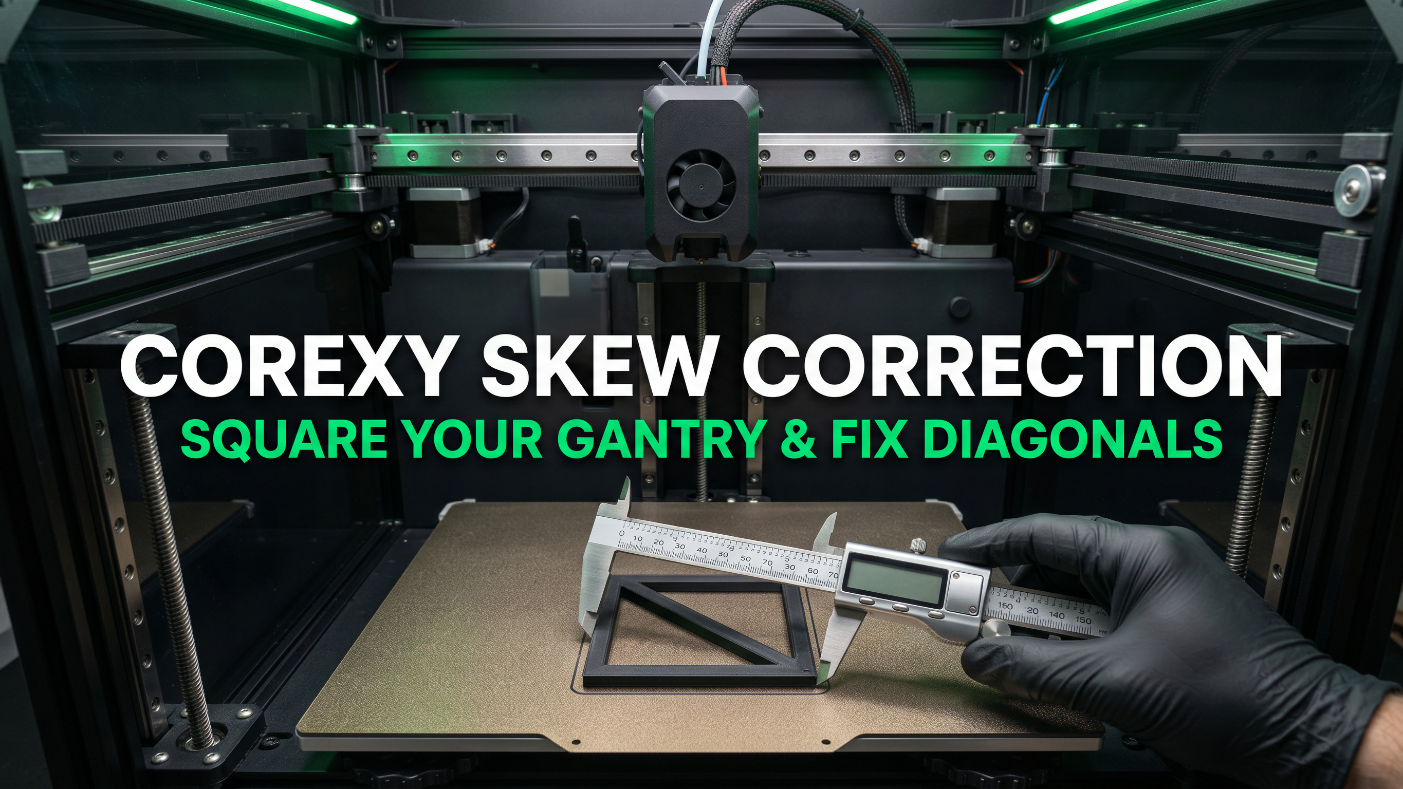
A 20 mm calibration cube can read 20.02 mm along X and 19.99 mm along Y while your printer is still quietly turning large functional prints into subtle parallelograms. Everything looks accurate on a small block because short edges hide angular drift, yet as soon as you print a 180 mm Gridfinity baseplate or a two-piece electronics housing, the lid binds or refuses to seat flush.
That mismatch happens when the X and Y motion axes sit at 89.5° or 90.4° instead of a true 90° right angle. On CoreXY machines like the Creality K1C, Elegoo Centauri Carbon, Bambu Lab P1S, or custom Voron builds, XY squareness depends directly on how evenly the two timing belts hold the X-gantry against the frame. One belt slightly looser than the other, or a gantry beam shifted by a single GT2 tooth during assembly, pulls the rail slightly askew.
Many makers try to patch this error by tweaking XY hole compensation or changing stepper rotation distance, which usually makes parts fit worse at other sizes. Fixing XY skew properly takes two stages in strict order: first measure your true diagonal error with calipers, square the physical gantry mechanically as close to zero as your hardware allows, and only then apply Klipper SET_SKEW or Marlin M852 compensation to erase the tiny remaining fraction of a millimeter.
Table of Contents
- Why Do CoreXY Prints Come Out Slightly Diamond-Shaped?
- Printing and Measuring a Diagonal Skew Test With Calipers
- Mechanical Fix First: Squaring the X-Gantry and Equalizing Belt Paths
- CoreXY Skew Diagnostic & Correction Matrix
- Maker Workshop Observations: Fixing a 0.65 mm Diagonal Error on My Bench
- Software Fine-Tuning With Klipper SET_SKEW, Marlin M852, and OrcaSlicer G-Code
- Frequently Asked Questions (FAQ)
- References & External Sources
Why Do CoreXY Prints Come Out Slightly Diamond-Shaped?
CoreXY printers produce diamond-shaped parts when unequal tension between the upper and lower A/B timing belts twists the floating X-gantry out of a 90° angle relative to the Y-axis rails. Even though X and Y step distances stay accurate, every Y move combines motion from both motors, so an angled crossbar turns rectangles into parallelograms.
Understanding why requires a quick look at how CoreXY kinematics differ from a traditional Cartesian printer. On a Cartesian bed-slinger, a single motor drives X and a separate motor drives Y independently along fixed extrusions. On a CoreXY gantry, two stationary rear motors work together through two long belts (commonly called Belt A and Belt B) to move one lightweight toolhead carriage:
- Pure X motion turns Motor A and Motor B in the same direction, keeping belt pull symmetric across the carriage.
- Pure Y motion turns Motor A and Motor B in opposite directions, relying on equal belt stiffness on both sides of the gantry to keep the X-rail perpendicular to the Y-rails.
- Diagonal 45° motion spins only one motor while the other holds position, sending all acceleration force down a single belt loop.
That last condition is where most printers drift over time. Think of the X-gantry like a long drafting T-square sliding up and down two parallel rulers: if one side lags behind the other by even half a millimeter, every vertical line still looks straight on its own, yet the corner angle shifts away from 90°.
Several hardware conditions trigger this racking effect on enclosed CoreXY frames:
- Uneven A/B belt tension after shipping or break-in: New GT2 belts stretch slightly during their first 30 to 50 print hours, especially around tight front idlers. If one belt settles more than the other, the higher-tension belt pulls its side of the X-rail slightly forward or back whenever motors engage.
- One skipped belt tooth during maintenance: Removing a motor mount, bumping the toolhead violently against a clipped purge bin, or unthreading a belt during hotend work can let one belt jump a 2 mm GT2 tooth relative to the frame.
- Twisted sheet-metal or injection-molded gantry brackets: On mid-range machines, small tolerances in idler housings or linear rail mounting holes often introduce 0.2° to 0.4° of built-in twist straight out of the factory box.
- Thermal expansion of enclosed frames: Printing engineering filaments such as ABS or ASA at 50°C to 60°C chamber temperatures can shift tension slightly if one belt path runs near a warm stepper motor while the other stays cooler.
"Never reach for firmware skew correction to hide a heavily racked CoreXY gantry. Software compensation tilts your stepper coordinates to match crooked rails, which increases belt stress and leaves ringing or binding on fast diagonal moves. Get the physical gantry within 0.20 mm across diagonals first, then let Klipper or Marlin polish out the final fraction."
Printing and Measuring a Diagonal Skew Test With Calipers
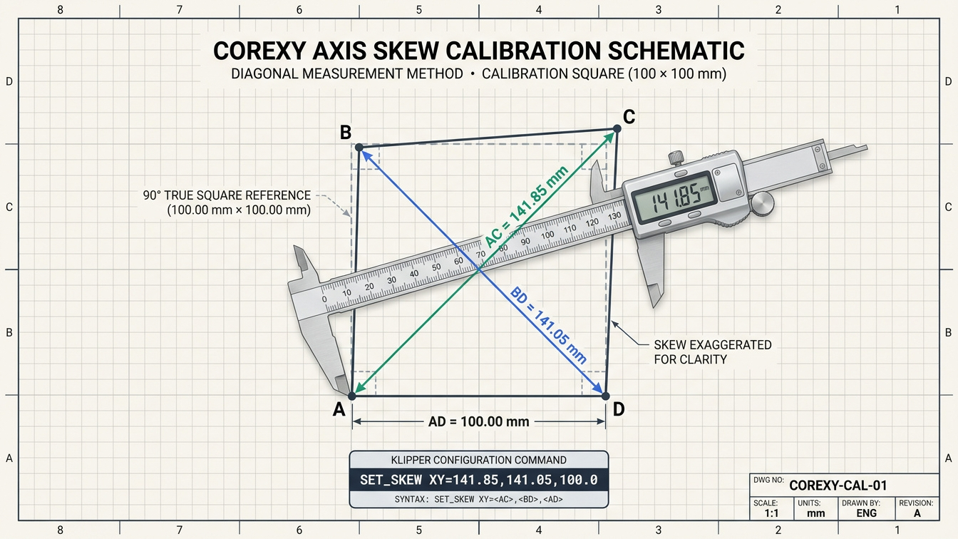
To measure XY skew accurately, print a rigid 100 mm calibration square or octagonal skew gauge oriented with corner A at the front-left bed origin, let it cool on the build plate, and compare the two diagonal lengths AC and BD with digital calipers. Any difference between AC and BD reveals out-of-square axes even when side AD measures exact.
A tiny 20 mm test cube cannot reliably expose skew because a 0.4° angular error across 20 mm shifts the diagonal by less than 0.14 mm—well within normal corner bulging and pressure-advance tolerances. Testing across a 100 mm × 100 mm span magnifies that same angle into a measurable 0.60 mm to 1.00 mm diagonal gap that standard 150 mm workshop calipers detect right away.
1. Prepare a Clean Test Profile
Before slicing your calibration square (such as the standard Klipper skew octagon, a 100 mm hollow frame, or a Califlower-style calibration plate), disable any active software skew compensation so you are measuring raw mechanical geometry. In Klipper, run SET_SKEW CLEAR=1 in the console or ensure no SKEW_PROFILE LOAD line runs in your start G-code. In Marlin, send M852 I0 temporarily before starting the print.
Slice the part with rigid, low-shrinkage filament rather than ABS or nylon, since thermal contraction can warp thin test arms during cooling. Sunlu PLA+ or Polymaker PolyLite PLA works well at 215°C nozzle temperature and 60°C bed temperature on a textured PEI sheet. Use 3 wall loops, 0.20 mm layer height, moderate outer wall speed around 100 mm/s, and ensure your pressure advance is tuned cleanly so bulbous corners don't skew your caliper jaws.
2. Orient Corner A Toward the Origin
Most CoreXY machines place the X0, Y0 origin at the front-left corner of the build plate (though some firmwares place it at the rear or center). Always mark the printed part directly on the build plate with a silver paint pen or fine permanent marker before lifting it off the PEI sheet:
- Corner A: Front-left corner (closest to X0, Y0).
- Corner B: Rear-left corner (along +Y from A).
- Corner C: Rear-right corner (diagonally opposite A).
- Corner D: Front-right corner (along +X from A).
Wait until the heated bed cools below 30°C so the PLA frame releases freely on its own. Pulling a warm PLA square off a magnetic PEI sheet bends the thin corners and ruins your measurement.
3. Measure AC, BD, and AD Carefully
Using clean 150 mm or 200 mm digital calipers, take three measurements on the flat side walls of the test print, avoiding any bottom elephant's-foot lip or top chamfer:
- Diagonal AC: Measure from outside corner A to outside corner C (or between dedicated diagonal measurement pads on a Califlower-style print). Record the average of three firm, flat readings.
- Diagonal BD: Measure from corner B to corner D the exact same way.
- Side AD: Measure the straight X-axis edge between A and D, resting the caliper jaws squarely along the flat faces rather than on corner chamfers.
On a true 100.00 mm square with zero skew, both diagonals measure $\sqrt{100^2 + 100^2} \approx 141.42\text{ mm}$. If your calipers read AC = 141.85 mm and BD = 141.05 mm while AD = 100.00 mm, your XY plane has a diagonal delta of 0.80 mm—roughly 0.32° of skew. Even if you scale X and Y steps, that 0.80 mm twist will break snap-fit tabs and screw patterns on wide parts.
Mechanical Fix First: Squaring the X-Gantry and Equalizing Belt Paths
Squaring a CoreXY gantry mechanically starts with loosening both A/B belt tensioners until the belts go slack, seating the X-beam evenly against the front frame stops with matching spacer blocks, and tightening both tensioners symmetrically until their vibration frequencies match. Doing this first removes physical racking and lowers belt drag.
Software skew correction is powerful, but it cannot cure a skewed belt path that binds linear rail bearings or makes one stepper motor pull harder than the other. Before typing a single G-code command, inspect and square the hardware itself.
Step 1: Print Two Identical Front Spacer Blocks
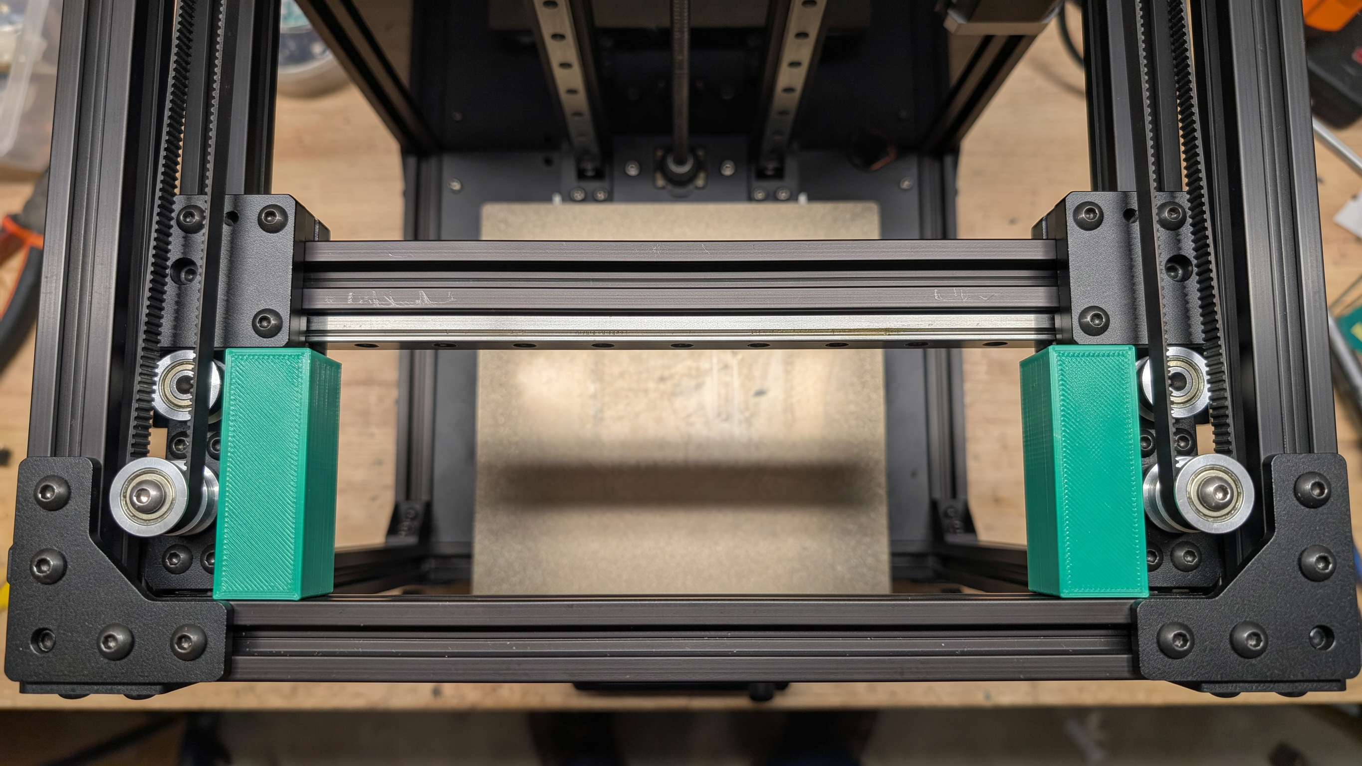
Print a pair of solid 20 mm × 20 mm × 40 mm calibration blocks (or dedicated gantry squaring clips designed for your frame) side by side near the center of your bed so both blocks share identical dimensions. Before you touch the belts, power off the printer and pull the X-gantry forward by hand toward the front frame extrusions or front idler brackets, inserting one spacer block on the left end and the other on the right end.
Hold the left block snug against the front idler housing with gentle finger pressure. Now check the right block: if it slides loosely with a visible 0.5 mm to 1.0 mm gap, or refuses to fit because the right side bottoms out early, your X-gantry is physically racked by the belt loop.
Step 2: Slacken Belts and Check Raw Gantry Alignment
Back out both rear or front A/B belt tensioner screws evenly by 6 to 8 full turns so neither belt forces the carriage into a twist. With the belts completely slack, repeat the spacer-block check against the front frame stops:
- If the X-gantry now sits dead flat against both spacers with zero gap: Your aluminum frame and linear rails are straight. The skew came strictly from uneven belt tension or a slipped tooth, which equalizing the belts will solve.
- If a gap remains even with slack belts: Loosen the 2 or 4 bolts clamping the X-rail to the left and right Y-carriage blocks slightly (just a quarter-turn, without stripping threads), square the X-beam firmly against both identical front spacers, and re-torque the carriage bolts in an alternating cross pattern. Inspect the vertical frame corner gussets too, because a loose 2020 extrusion screw can pull the entire Y-axis frame out of square.
Step 3: Tension Both Belts Symmetrically
Hold or lightly clamp the X-gantry square against your front spacers (or let balanced tension pull it cleanly once seated) and slowly tighten Belt A and Belt B in alternating half-turn increments. You don't want one side pulled tight while the other is still slack, because that instantly drags one carriage forward.
Once the belts feel firm, move the toolhead to a repeatable center-front reference position (for example, 150 mm from the front belt clamp on both the upper and lower belt spans) and pluck each belt lightly like a guitar string using a smartphone frequency tuner app or a dedicated belt tension meter. On most 250 mm to 300 mm desktop CoreXY printers using 6 mm GT2 belts, matching both belts within 2 Hz to 3 Hz around the manufacturer's target (commonly 100 Hz to 115 Hz depending on span length) keeps the gantry square and avoids VFA artifacts. For a deeper walkthrough on tuning belt pitch and resonance graphs, read our guide on balancing CoreXY belt tension and fixing VFA ringing.
After re-tensioning, move the toolhead slowly back and forth across the full Y travel by hand (keep movements slow so back-EMF from the steppers doesn't spike the control board). Verify that motion feels completely smooth from rear to front and re-check with the front spacer blocks—both sides should now meet the stops at the exact same moment.
CoreXY Skew Diagnostic & Correction Matrix
Use the diagnostic matrix below to classify your caliper measurements across a 100 mm calibration square and decide whether to adjust hardware first or move straight to firmware compensation.
| Diagonal Delta (|AC - BD| on 100 mm) | Estimated Skew Angle | Visible Part Symptom | Likely Root Cause | Recommended Mechanical Action | Firmware Compensation Action |
|---|---|---|---|---|---|
| 0.00 – 0.08 mm | < 0.03° | Interlocking bins and bearing bores fit as designed | Normal belt tolerance and print edge variance | No mechanical adjustment required | Optional; skip SET_SKEW unless machining tight jigs |
| 0.09 – 0.25 mm | 0.04° – 0.10° | Slight corner rock on 200 mm Gridfinity lids or press-fit pins | Minor factory bracket tolerance or slight belt stretch | Quick belt frequency check (~2–3 Hz match) | Ideal range for Klipper SET_SKEW or Marlin M852 |
| 0.26 – 0.55 mm | 0.11° – 0.22° | Multi-bolt flanges bind near outer holes; square frames look visibly off | Asymmetric A/B belt tension after break-in or hotend swap | Equalize A/B tensioners and check front spacer gap | Apply SET_SKEW only after re-tensioning reduces delta |
| 0.56 – 1.10 mm | 0.23° – 0.45° | Clear parallelogram skew on 150 mm trays; Y bearings feel tight | X-gantry racked by 1 belt tooth or loose carriage bolts | Slacken belts, square X-beam on spacers, re-torque mounts | Do not mask with firmware alone; fix hardware first |
| > 1.10 mm | > 0.45° | Parts visibly crooked; carriage stalls or grinds near corners | Twisted 2020 frame extrusions, slipped pulley grub screw, or bad idler | Inspect frame corner brackets, pulley set screws, and idlers | Firmware skew unsafe until mechanical bind is cleared |
| Varies by Bed Zone | Inconsistent | Left half prints square while right half shifts diagonally | Loose belt clamp teeth, frayed GT2 belt cord, or bent rod/rail | Replace stretched GT2 belt and inspect linear rail screws | Static skew profile cannot fix non-linear belt slip |
CoreXY Printers, Replacement GT2 Belts & Calibration Hardware
If a worn GT2 belt, chipped flanged idler pulley, or sloppy gantry mount keeps pulling your frame out of square after repeated tensioning, swapping fresh low-stretch components saves hours of chasing phantom slicer errors. Check our regularly updated 3D Printing Deals & Coupons page for current hardware savings alongside our recommended CoreXY printers and spare motion parts below.
Maker Workshop Observations: Fixing a 0.65 mm Diagonal Error on My Bench
Maker's Workshop Note: Resolving Parallelograms Across Functional Enclosures
In my workshop tests building modular workshop organizers and two-piece controller housings, small calibration cubes misled me more than once. A 20 mm cube off my Creality K1C measured 20.01 mm along X and 19.98 mm along Y, so I assumed the motion system was dialed in. The surprise came after a four-hour print of a 140 mm × 140 mm electronics cover in Polymaker PolyLite PLA (215°C hotend, 60°C textured PEI bed): the screw bosses lined up along one side and missed their mating holes by more than half a millimeter on the opposite corner.
I printed a 100 mm skew frame and checked the diagonals with 150 mm Mitutoyo-style digital calipers after letting the plate cool completely. Diagonal AC read 141.74 mm while diagonal BD read 141.09 mm—a 0.65 mm diagonal gap despite clean linear edges. Checking the front stops with two matching 3D-printed spacer blocks immediately revealed the culprit: the right side of the X-gantry touched the front mount while the left side still showed roughly a 0.7 mm gap, and Belt B plucked noticeably lower in pitch than Belt A.
I backed out both rear tensioners on my printer, slightly loosened the four screws holding the X-rail to the Y-blocks, seated both ends evenly against the spacer blocks, and brought both belts back up evenly to matching tone around 108 Hz. Reprinting the exact same 100 mm square dropped the diagonal error from 0.65 mm down to 0.14 mm (141.49 mm vs. 141.35 mm)—already within reasonable snap-fit tolerance for eSUN PETG brackets printed at 240°C and 80°C bed. Adding a light Klipper SET_SKEW profile brought the final reprint diagonals to 141.43 mm and 141.40 mm (0.03 mm difference), and every mating lid since then drops straight onto its mounting posts without forcing the bolts.
I ran the same front-spacer check on my Elegoo Centauri Carbon as part of routine preventative maintenance after its first 120 hours of high-speed PLA printing. That machine only had a 0.16 mm diagonal variance from the factory, so leaving the hardware untouched and adding a small Klipper skew entry cleanly closed the remaining gap without loosening any gantry bolts.
Software Fine-Tuning With Klipper SET_SKEW, Marlin M852, and OrcaSlicer G-Code
After squaring your gantry mechanically, software skew correction applies an exact coordinate transform in firmware to remove the remaining sub-0.25 mm diagonal error. In Klipper, enable [skew_correction] in printer.cfg, enter your measured AC, BD, and AD values via SET_SKEW, save a named profile, and load it after homing in OrcaSlicer.
Once physical alignment brings your 100 mm diagonal gap below 0.25 mm, chasing the last 0.10 mm with pliers and feeler gauges gets frustrating because bolt-hole clearances shift slightly every time you torque a screw. Firmware skew correction handles those tiny remaining angles cleanly and reproducibly.
1. Setting Up Klipper [skew_correction]
Open your printer.cfg file in Mainsail or Fluidd and add an empty section header anywhere before the auto-generated #*# <---------------------- SAVE_CONFIG --------------------> block:
[skew_correction]Click Save & Restart. Next, verify that your test print measurements were captured without skew active (using SET_SKEW CLEAR=1 prior to printing). Suppose your cooled 100 mm test frame measured AC = 141.85, BD = 141.05, and AD = 100.0. Enter those exact three numbers into the Klipper console:
SET_SKEW XY=141.85,141.05,100.0
SKEW_PROFILE SAVE=my_skew_profile
SAVE_CONFIG
Klipper computes the XY skew factor automatically from your three lengths and writes the profile parameters to the bottom of printer.cfg when SAVE_CONFIG restarts the firmware. If your printer runs a calibrated multi-plane test block that also measures vertical Z lean, you can include XZ and YZ measurements in the same command: SET_SKEW XY=141.85,141.05,100.0 XZ=141.6,141.4,100.0 YZ=141.5,141.3,100.0.
2. Loading and Clearing Skew Safely in OrcaSlicer
Klipper does not load a saved skew profile automatically at boot, and leaving skew active during edge travel moves can create subtle issues. Per Klipper's official documentation, always load your profile in your slicer's Machine start G-code after homing (G28), bed meshing, and any edge purge line or nozzle wipe near the bed perimeter, and clear it at the end of every print:
; Place at the end of Machine start G-code (after G28 and purge line)
SKEW_PROFILE LOAD=my_skew_profile

; Place at the beginning of Machine end G-code
SET_SKEW CLEAR=1
Keeping SKEW_PROFILE LOAD after your purge line is important: because skew math slightly shifts X and Y coordinates to square up diagonals, placing a part or purge strip right against the physical 0 mm or 256 mm travel limits can push the corrected coordinate outside Klipper's configured position_min / position_max bounds and trigger a Move out of range error. When printing near full bed capacity with skew correction enabled, leave a 3 mm to 5 mm safety margin around the outer bed edges in OrcaSlicer.
3. Verifying Your Correction With CALC_MEASURED_SKEW
Reprint your 100 mm calibration square with my_skew_profile active, let it cool on the build plate, and measure AC, BD, and AD again. Do not feed the new measurements back into SET_SKEW—instead, verify the remaining error using Klipper's built-in verification helper:
GET_CURRENT_SKEW
CALC_MEASURED_SKEW AC=141.43 BD=141.40 AD=100.0
GET_CURRENT_SKEW prints the active radians/tan skew factor currently applied, while CALC_MEASURED_SKEW calculates the residual skew still left on your reprinted test part. If the residual reading sits close to zero (typically within ±0.0005 rad or under 0.05 mm difference between AC and BD), your calibration is done. If you still see an offset, clear skew with SET_SKEW CLEAR=1, take a fresh baseline measurement, and double-check that corner A really faced the origin during measurement (swapping AC and BD doubles the skew in the wrong direction).
4. Applying Skew Compensation in Marlin Firmware (M852)
For CoreXY machines running Marlin rather than Klipper, bed skew correction works through the M852 command (provided SKEW_CORRECTION and SKEW_CORRECTION_GCODE are enabled in Configuration.h). Marlin takes a direct tan-theta skew factor I rather than raw diagonal lengths, calculated from your measurements with the standard formula:
AC_side = sqrt(2 * AC^2 + 2 * BD^2 - 4 * AD^2) / 2
tan_skew = (AC^2 - BD^2) / (4 * AD * AC_side)
For small angles where AD and the perpendicular side AB are both close to 100 mm, that simplifies closely to (AC - BD) / (sqrt(2) * 100)—for example, AC = 141.85 and BD = 141.05 yields roughly +0.00566 (or -0.00566 depending on sign convention, which a quick verification reprint confirms immediately). Send the factor and store it permanently in EEPROM:
M852 I0.00566
M500
Once your XY squareness is locked in, finish your dimensional checks by running a dimensional 3D print quality test to confirm extrusion flow and shrinkage compensation match your calibrated axes.
Related Guides & Next Steps
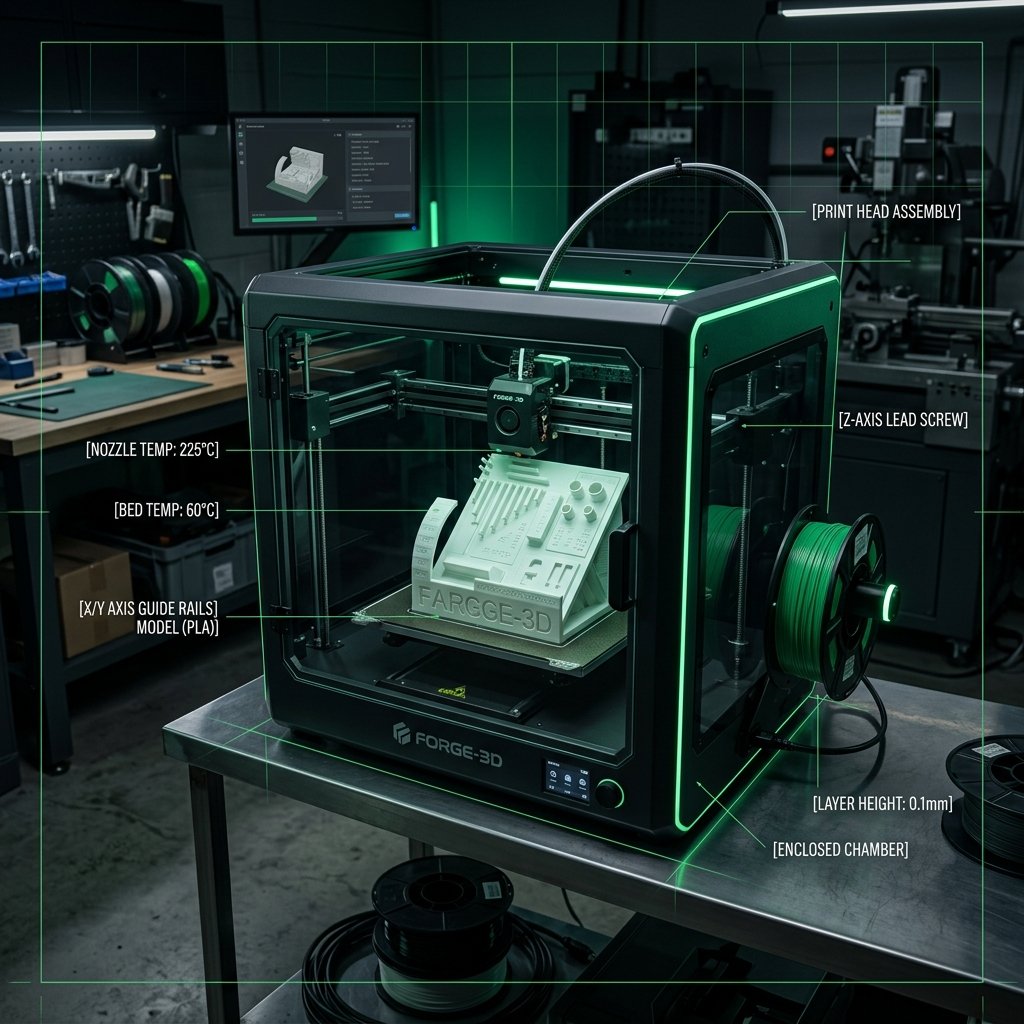
3D Print Quality Test: How to Calibrate Your FDM Printer
Achieving high-quality prints requires tuning your FDM printer settings. Learn the top test models—like calibration cubes, torture tests, and temperature towers—and how to read their results to fix common printing issues.
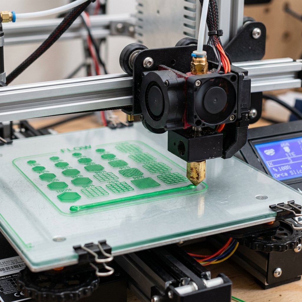
How to Calibrate Filaments in Orca Slicer: Full Guide
A comprehensive, step-by-step tutorial on using Orca Slicer's built-in tools to calibrate flow rate, temperature, and pressure advance for third-party filaments.
Frequently Asked Questions (FAQ)
1. Can I fix diamond-shaped prints by calibrating rotation_distance or XY steps/mm?
No. Adjusting rotation_distance in Klipper or steps/mm in Marlin only scales the overall length along X or Y; it cannot change the 90° angle between the two axes. If your cube edges are already close to 20.00 mm and only the diagonals differ, changing steps/mm will break linear dimensions without making corners square.
2. Should I run Klipper SET_SKEW if my CoreXY diagonals are off by only 0.10 mm?
On a 100 mm span, a 0.10 mm difference between AC and BD corresponds to roughly 0.04° of skew, which rarely affects decorative models or loose-tolerance brackets. However, if you print full-plate Gridfinity bins, gears, or interlocking enclosures over 180 mm wide, applying SET_SKEW takes five minutes and removes even that subtle fit error.
3. Why did Klipper throw a "Move out of range" error right after I enabled SKEW_PROFILE LOAD?
Skew compensation applies a slight coordinate shear across X and Y to turn tilted hardware into square parts. If your start G-code runs a purge line at X=0.5 or Y=2, or if you place a large print flush against the bed edge, the corrected target coordinate can dip below 0 or exceed position_max. Load your skew profile after homing and purge lines, and leave a 3 mm to 5 mm margin around the perimeter of your print bed.
4. What happens if I swap AC and BD by mistake in SET_SKEW?
Reversing AC and BD mirrors the correction direction and doubles your diagonal error instead of eliminating it. Always double-check that Corner A faces your printer's X0/Y0 origin, B sits along +Y, C sits diagonally across from A, and D sits along +X before running SET_SKEW, then verify on a fast reprint with CALC_MEASURED_SKEW.
5. Do I need to re-run skew calibration after changing filaments or nozzles?
Swapping nozzles or switching between PLA and PETG does not change your CoreXY gantry angle, though thermal shrinkage in ABS or ASA can alter linear dimensions uniformly across all axes (which belongs in your slicer's filament shrinkage setting rather than SET_SKEW). Only re-run skew calibration after adjusting A/B belt tension, replacing belts or idlers, or disassembling the toolhead gantry.
References & External Sources
- Klipper Official Documentation: Skew Correction Setup and Measurement Guide
- Klipper Official Documentation: G-Codes Reference (SET_SKEW, SKEW_PROFILE, CALC_MEASURED_SKEW)
- Marlin Firmware Documentation: M852 Bed Skew Compensation Command
- Prusa Knowledge Base: Adjusting CoreXY Belt Tension and Checking Gantry Squareness
About the Author: Dinu Suciu
I am Dinu Suciu, founder and prototyping specialist at 3D Print Book. Operating an active maker workshop equipped exclusively with desktop FDM 3D printers—including high-speed enclosed CoreXY machines and multi-material systems—I focus on mechanical accuracy, preventative machine maintenance, and repeatable print workflows for functional parts. Have a question about CoreXY tuning or custom prototyping? Reach out directly through our Contact Page.