Few alarms in desktop 3D printing trigger as much frustration as a sudden mid-print shutdown accompanied by a piercing beep and a screen flashing MINTEMP, MAXTEMP, or Thermal Runaway. You might be twelve hours into a complex multi-part functional print, watching layers stack cleanly at 300 mm/s, when the motion suddenly freezes and the controller board cuts heater power entirely.
While an unexpected shutdown is inconvenient, these thermal safeguards are among the most critical protective systems built into modern FDM firmware. An aluminum heater block powered by a 40W, 50W, or high-output 60W ceramic heating element can reach temperatures exceeding 400°C in less than two minutes if left uncontrolled. At those temperatures, aluminum blocks soften, silicone socks incinerate, and nearby printed fan ducts catch fire. When the control board halts your machine, it is executing an intentional emergency stop because its sensor feedback loop no longer makes physical sense.
Resolving these alarms requires methodical electrical testing rather than guessing or repeatedly power-cycling the machine. Swapping random components without checking circuit continuity often leaves hidden wire fractures undiscovered, resulting in another halted print hours later. In this workshop guide, we examine the physics behind NTC 100K sensors, demonstrate how to perform conclusive resistance checks using a standard digital multimeter, isolate mechanical wire pinch points, and recalibrate control loops to ensure reliable, safe operation.
Table of Contents
- What Causes MINTEMP and Thermal Runaway Alarms on FDM Printers?
- How NTC 100K Thermistors Work and Common Mechanical Failure Points
- Multimeter Resistance Checks for NTC 100K Thermistors
- Fixing Overtightened Screws, Broken Ferrules, and Loose Heaters
- Diagnostic Matrix: Symptoms, Root Causes, and Step-by-Step Fixes
- Maker Workshop Observations: Real Troubleshooting Logs from My Bench
- When to Replace the Hotend Harness and Re-Run PID Tuning
- Frequently Asked Questions (FAQ)
- References & External Sources
What Causes MINTEMP and Thermal Runaway Alarms on FDM Printers?
MINTEMP alarms occur when firmware detects an open circuit or infinite resistance on a temperature sensor channel, while Thermal Runaway alarms trigger when the hotend or heated bed fails to heat up within expected rate limits or drifts outside target tolerances while power is applied.
Every open-source and proprietary 3D printer controller runs a continuous verification loop inside its temperature management code. In Marlin, this routine is governed by thermal protection thresholds configured in Configuration_adv.h. In Klipper, the behavior is dictated by the [verify_heater heater_config_name] stanza. Despite slight differences in terminology across firmware implementations, both systems monitor three primary failure conditions:
- The Open-Circuit Trip (MINTEMP): When a thermistor lead wire snaps inside an umbilical harness or pulls free from a terminal block, electrical resistance across the sensor input pins climbs toward infinity. In a standard Negative Temperature Coefficient (NTC) thermistor circuit, high resistance corresponds to sub-zero temperatures. If the readout drops below the configured floor (usually 0°C or -14°C), the firmware assumes the sensor wire is physically severed and immediately shuts down the machine to prevent blind heating.
- The Short-Circuit Trip (MAXTEMP): If the two bare lead wires of a thermistor touch each other or short out against a grounded metal heater block, electrical resistance plummets to near zero ohms. The microcontroller translates this near-zero resistance as an impossibly high temperature reading (typically 300°C to 350°C+). The firmware trips a MAXTEMP error instantly, shutting down heater MOSFETs to prevent hardware destruction.
- The Inadequate Heating Rate Trip (Thermal Runaway): If the microcontroller commands 100% duty cycle to the heater cartridge, it expects the measured temperature to rise by a minimum number of degrees (e.g., 2°C every 20 seconds). If a cartridge has slipped out of the aluminum block, if a silicone sock is missing during high-flow part cooling fan engagement, or if a heater wire has failed under load, the block will not warm up as expected. The firmware interprets this discrepancy as an unmonitored heating element and cuts power before the decoupled cartridge can ignite surrounding components.
- The Temperature Droop Trip: Even after reaching an extrusion temperature of 215°C or 250°C, the controller continuously verifies that the sensor remains within a narrow hysteresis window (commonly ±4°C or ±8°C). If high chamber drafts or an erratic sensor connection causes the reading to dive below this envelope for more than a few seconds, thermal runaway protection interrupts the print.
"Treat thermal runaway errors as critical safety notifications rather than nuisance interruptions. Never increase firmware timeout thresholds to mask an intermittent sensor or heater fault; physical inspection is the only legitimate path to recovery."
How NTC 100K Thermistors Work and Common Mechanical Failure Points
NTC 100K thermistors are ceramic semiconductor resistors whose electrical resistance decreases predictably as temperature increases, making their ultra-thin sensor leads highly vulnerable to mechanical stress and metal fatigue under rapid toolhead motion.
The vast majority of consumer and semi-professional FDM 3D printers employ a nominal 100kΩ thermistor (typically utilizing the common Beta 3950 or Semitec 104GT-2 / 104NT-4-R025H42G calibration curves). At a standard room temperature of 25°C (77°F), a healthy sensor exhibits an electrical resistance of approximately 100,000 ohms across its two terminals. As the heater cartridge warms the aluminum or plated copper block to a printing temperature of 210°C, the internal resistance of the thermistor drops drastically to roughly 1,000 to 1,500 ohms. At 250°C, that resistance falls further to roughly 500 ohms.
The mainboard reads this resistance through a voltage divider circuit consisting of a precise 4.7kΩ pull-up resistor connected to a stable 3.3V or 5V reference rail. An analog-to-digital converter (ADC) samples the resulting analog voltage, and firmware converts that voltage into a Celsius temperature using a precompiled mathematical look-up table.
Because the temperature-sensing element is fundamentally an electrical resistor, anything that alters resistance along the entire wire run—from the sensor bead to the mainboard header—corrupts the temperature reading. In high-speed desktop printers, several distinct mechanical failure mechanisms occur routinely:
- Glass Bead Lead Shearing: Traditional V6-style and MK8 heater blocks utilize a tiny 1 mm glass bead thermistor. The transition point where the micro-fine platinum or alloy leads emerge from the glass bead is mechanically brittle. Bending these leads at sharp 90-degree angles during installation causes micro-fractures inside the glass envelope.
- Continuous Flex Fatigue in Drag Chains and Umbilicals: Modern CoreXY and high-acceleration bed-slingers subject the toolhead wire harness to violent reciprocal bending cycles at 15,000 to 20,000 mm/s² acceleration. Copper wire strands inside flexible umbilical sleeves undergo work hardening over hundreds of printing hours. Individual copper strands snap one by one inside the PVC or PTFE insulation. The wire remains connected while stationary, but breaks continuity momentarily whenever the toolhead sweeps to a specific X or Y coordinate.
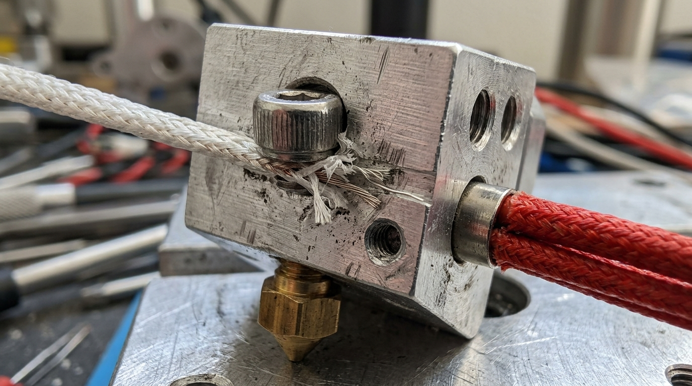
- Pinched Insulation Against Metal Edges: Many budget toolheads secure the thermistor using a standard M3 pan-head screw and flat washer. Overtightening this screw crushes the braided fiberglass sleeving, driving the screw edge into the sensor conductors and creating an intermittent short against the grounded metal block.
- Creep and Solder Softening on Terminal Boards: Certain toolhead breakout boards utilize soldered screw terminals or JST connectors positioned within centimeters of the heat sink. Radiated chamber heat and repeated thermal expansion cycles loosen terminal screws and induce solder joint cracks (cold solder joints) on surface-mount header pins.
Multimeter Resistance Checks for NTC 100K Thermistors
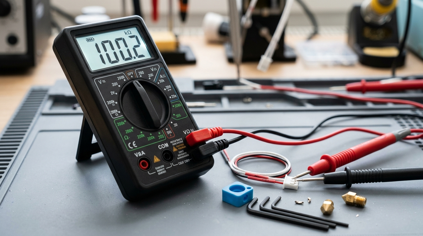
To diagnose an NTC 100K thermistor conclusively, disconnect the 2-pin connector from the toolhead or mainboard, select the 200kΩ resistance scale on a digital multimeter, and verify that the sensor reads between 95kΩ and 105kΩ at 25°C ambient temperature.
Relying solely on on-screen LCD readouts can be misleading because firmware filtering routines and moving averages smooth out rapid intermittent spikes. A calibrated multimeter allows you to inspect the raw physical resistance of the circuit directly. Follow this five-step diagnostic protocol:
Step 1: Room Temperature Baseline Measurement
Power off the 3D printer completely and unplug the power cord from the wall outlet. Allow the toolhead to cool to ambient room temperature. Locate the 2-pin thermistor connector—either at the toolhead breakout board (on CoreXY toolheads like those in the Creality K1 or Bambu series) or directly at the mainboard (labeled TH0, TEMP_0, or TE0).
Set your digital multimeter to measure resistance (Ohms). If your meter has manual range selection, select the 200kΩ range. Touch the fine meter probes to the metal crimp terminals inside the disconnected 2-pin female housing. At a comfortable room temperature of 20°C to 25°C (68°F to 77°F), your reading should settle between 95kΩ and 115kΩ. If the meter displays "OL", "1", or infinite resistance, one of the conductors is completely severed (the root cause of MINTEMP). If the meter displays 0.00Ω or a few ohms, the leads are shorted together (the cause of MAXTEMP).
Step 2: Thermal Response Directional Check
While keeping the multimeter probes firmly pressed against the connector terminals, grasp the aluminum heater block with your bare fingers or hold a warm mug against it for 15 seconds. Because this is a Negative Temperature Coefficient resistor, the natural warmth of your hand must cause the displayed resistance to steadily drop—typically from 100kΩ down to 88kΩ or 82kΩ. If the resistance does not respond to temperature changes or jumps erratically by tens of thousands of ohms, the internal semiconductor element has degraded and the sensor must be replaced.
Step 3: Harness Flex and Wiggle Test (Catching Intermittent Open Circuits)
The most deceptive faults are intermittent open circuits that read a perfect 100kΩ when the machine is idle but fail under dynamic motion. To catch these faults, leave your multimeter connected across the terminals while your meter is set to resistance (or continuity mode with an audible tone). Slowly manipulate the wire harness by hand:
- Gently flex the cable bundle right where it exits the toolhead strain relief.
- Flex the cable at the entrance and exit of the plastic drag chain or umbilical spine.
- Slide the toolhead manually across the entire X-axis gantry while monitoring the meter screen.
If the reading flickers, drops out to "OL", or jumps wildly during any portion of the motion arc, you have located an internal copper fatigue fracture inside the harness jacket.
Step 4: Chassis Ground Isolation Test
A damaged thermistor wire often shorts to the aluminum block or printer chassis ground only when the heater heats up and expands. Set your multimeter to the continuity buzzer or lowest resistance scale (200Ω). Place one probe on one of the thermistor pins and the second probe against bare aluminum on the heater block (or against the toolhead mounting bracket). Repeat the test for the second thermistor pin. Both pins must show an open circuit (infinite resistance) to ground. Any continuity or measurable resistance between a thermistor conductor and the aluminum block indicates that the insulating fiberglass sleeve or Kapton tape has been breached, creating an active ground short.
Step 5: Heater Cartridge Resistance Check
Because thermal runaway alarms can also stem from an open or degraded heating element, measure the heater cartridge resistance across its two power leads while disconnected from the board. Use the 200Ω scale. Applying Ohm's Law ($R = \frac{V^2}{P}$):
- A standard 24V, 40W heater cartridge should measure approximately 14.4 ohms ($\pm 1.5\Omega$).
- A high-output 24V, 50W cartridge should measure approximately 11.5 ohms ($\pm 1.0\Omega$).
- A rapid ceramic 24V, 60W heater ring should measure approximately 9.6 ohms ($\pm 0.8\Omega$).
- A legacy 12V, 40W cartridge should measure approximately 3.6 ohms.
If your multimeter indicates infinite resistance across the heater cartridge wires, the internal nichrome heating coil has burned out, meaning the controller cannot deliver thermal energy despite sending full pulse-width modulation (PWM) power.
Fixing Overtightened Screws, Broken Ferrules, and Loose Heaters
Proper mechanical installation requires securing thermistors without over-compressing fiberglass insulation sleeves, applying high-temperature boron nitride paste for heat transfer, and ensuring heater clamping grub screws are tightened while hot.
Most thermistor failures originate during nozzle changes or hotend rebuilds rather than spontaneous electrical breakdowns. When reinstalling or replacing hotend hardware, observe the following physical assembly rules:
1. The Delicate M3 Thermistor Screw Collar
On traditional heater blocks (E3D V6 clones, Creality Ender, and older Prusa blocks), the thermistor bead sits inside a drilled blind hole and is retained by a washer head screw. Never tighten this screw with full torque. The screw is intended solely as a retaining stop to prevent the sensor from sliding out of the cavity. Thread the screw in until the washer makes light contact with the white fiberglass sleeving, then stop immediately. If you observe the braided sleeve spreading or flattening significantly, you have already over-torqued the screw and risked crushing the internal conductor insulation.
2. Cartridge-Style Thermistors (The Modern Upgrade)
If your printer still uses fragile glass bead sensors, consider upgrading to a metal cartridge thermistor (such as a 3 mm × 15 mm stainless steel cartridge) or a screw-in M3 threaded brass thermistor. Cartridge thermistors encase the delicate ceramic element and solder joints inside solid ceramic potting compound protected by a stainless steel jacket. They resist mechanical crushing, handle high-acceleration g-forces without fatigue, and slide securely into heater blocks held by a grub screw rather than an abrasive washer head.
3. Applying Boron Nitride Thermal Paste
Air is a poor thermal conductor. A cylindrical sensor sitting in an oversized drilled hole in an aluminum block is insulated by microscopic air gaps. This air boundary introduces thermal lag: the heater element gets blistering hot before heat conducts into the thermistor. The firmware detects this lag as an unresponsive heating curve and trips thermal runaway protection during rapid warm-up cycles.
Before inserting a new thermistor cartridge or glass bead, coat the sensor lightly with boron nitride thermal grease (rated for 1,000°C+). Do not use standard PC CPU heatsink grease (like silver or zinc oxide compounds), which dries out and breaks down above 150°C. Boron nitride paste fills microscopic voids, eliminates temperature measurement latency, and prevents the sensor cartridge from seizing permanently inside the aluminum block due to high-temperature galvanic corrosion.
4. Thermal Expansion Set Screw Tightening
Heater cartridges and aluminum blocks have different coefficients of thermal expansion. Aluminum expands more rapidly than the stainless steel jacket of a cylindrical heater cartridge. If you tighten the heater cartridge grub screw while the block is cold, the cavity will loosen as the block heats up to 250°C. The cartridge can physically slide out during violent infill accelerations, leaving an active heater dangling outside the monitored block.
Always perform a final mechanical check of the cartridge retention screw at an elevated temperature. Heat the block to 200°C, hold the block firmly with an insulated wrench or pliers, and verify that the clamping grub screw is snug. Ensure the heater wires exit with a gentle strain relief curve rather than a taut bend against sharp metal edges.
Diagnostic Matrix: Symptoms, Root Causes, and Step-by-Step Fixes
The comparative matrix below outlines the primary error codes, observable LCD temperature behaviors, root electrical causes, and verified workshop repair protocols across desktop FDM machines.
| Fault Code / Display Error | LCD Temperature Reading | Root Electrical Cause | Multimeter Test Result | Physical Verification Check | Permanent Corrective Action |
|---|---|---|---|---|---|
| MINTEMP / Error: MINTEMP triggered | -14°C, 0°C, or blinking "ERR" | Open circuit; broken wire or disconnected plug | Infinite resistance ("OL" or > 500kΩ) | Unseated JST pin, severed wire inside umbilical | Re-crimp terminal pin or replace toolhead wiring harness |
| MAXTEMP / Error: MAXTEMP triggered | 300°C–350°C+ at cold boot | Direct short circuit across sensor leads | Near-zero resistance (0.00Ω to 20Ω) | Overtightened M3 screw crushing fiberglass sleeve | Loosen retaining screw, inspect wire jacket, replace bead |
| Thermal Runaway (During Initial Heating) | Stalls below target (e.g. stops at 165°C) | Insufficient heat input or severe thermal loss | Heater: Infinite resistance (open coil) or low voltage | Heater cartridge loose/slipped out, sock missing | Reseat cartridge with boron nitride; verify 24V supply |
| Thermal Runaway (When Fan Turns On) | Drops > 5°C immediately at layer 2/3 | Part cooling airflow blowing across bare block | Thermistor and heater measure normal resistance | Damaged, missing, or loosely fitted silicone sock | Install tight-fitting OEM silicone thermal insulation sock |
| Intermittent MINTEMP (Mid-Print) | Readout flickers violently (210°C to -10°C) | Dynamic flex fatigue fracture in cable harness | Resistance jumps to "OL" when wiggling drag chain | Wire flexing past minimum bend radius at gantry edge | Replace wire run with high-flex silicone or PTFE wire |
| Heater Decoupled / Bed Thermal Runaway | Bed heats slowly; drops under draft | Thermistor unbonded from underside of bed | Thermistor reads 100kΩ; heater reads 2.0–3.0Ω | Aluminum tape peeling beneath heated bed plate | Re-tape thermistor with Kapton tape & high-temp silicone |
Stock Up on Replacement Thermistors, Toolhead Spares & Workshop Gear
Keeping high-temperature NTC 100K cartridges, ceramic heating elements, silicone socks, and crimping kits on your workshop shelf ensures that a minor wire fatigue fracture never halts your production queue for days. Browse our curated 3D Printing Deals & Coupons page for verified discounts on replacement toolhead hardware, high-flex wiring components, and complete CoreXY hotend assemblies.
Maker Workshop Observations: Real Troubleshooting Logs from My Bench
Maker's Workshop Note: Diagnosing Intermittent Thermal Alarms on My FDM Printers
In my workshop tests across several enclosed CoreXY and open-frame FDM machines, I found that thermal alarms almost never indicate a damaged mainboard. In more than ninety percent of cases, the failure is entirely mechanical or related to thermal airflow management.
The Deceptive "Z-Height MINTEMP" on My Creality Printer: While running high-volume functional prints on my Creality printer, I ran into a maddening intermittent issue: prints would execute flawlessly for the first 50 millimeters of height, but would consistently trigger a MINTEMP halt once parts passed roughly 140 millimeters on the Z-axis. When I inspected the machine stationary on the bench, the hotend temperature readout was rock-solid at 215°C.
To isolate the fault, I hooked up my multimeter across the thermistor pins at the mainboard breakout while manually guiding the gantry upward. The moment the umbilical harness made a sharp bend around the upper aluminum frame extrusion at Z=145 mm, the meter reading snapped instantly from 1.2kΩ to "OL". One of the internal 28 AWG copper signal leads had developed a stress fracture beneath an unblemished outer PVC jacket. Replacing that section with high-strand-count silicone wire completely solved the issue.
The Missing Silicone Sock Trap: On another occasion, right after performing a high-flow nozzle swap on a high-speed toolhead, my printer tripped a thermal runaway alarm exactly at layer 3. The culprit was immediately clear once I analyzed the slicer profile: the slicer was configured to engage twin 5015 auxiliary cooling fans at 100% speed starting on layer 3. Because I had forgotten to reinstall the silicone thermal sock over the heater block after changing the nozzle, the intense downdraft from the cooling fans was stripping heat faster than the 40W heater cartridge could replenish it. Reinstalling a snug silicone sock stabilized the block temperature within ±0.4°C of target and prevented further fan-induced thermal droops.
When to Replace the Hotend Harness and Re-Run PID Tuning
Whenever you replace a thermistor, swap a heater cartridge, or install a new wiring harness, executing a fresh PID auto-tune calibration is mandatory to train firmware compensation algorithms on your new thermal hardware characteristics.
Temporary wire splices inside a toolhead cable chain rarely hold up under continuous high-speed printing. Twisting wires together or joining micro-conductors with stiff solder joints creates localized stress risers that fracture within dozens of operating hours. When an umbilical wire fails:
- Use Proper Multi-Strand Wire: Replace signal leads with high-flexibility 24 AWG or 26 AWG silicone-insulated wire (featuring 0.05 mm or 0.08 mm copper stranding) or PTFE-jacketed industrial automation wire rated for millions of continuous bend cycles.
- Crimp Fresh JST Terminals: Use dedicated ratcheting crimping pliers (such as an Engineer PA-09 or IWISS crimper) to seat genuine JST-XH or Micro-Fit terminal pins. Ensure the strain relief tabs grip the wire insulation jacket firmly rather than clamping bare copper strands.
- Protect Toolhead Boards: Take care when working around live electronics; as detailed in our guide on preventing electrical toolhead shorts, accidentally touching a live heater lead to an adjacent thermistor signal trace will instantly destroy the microcontroller's analog ADC input pin.
Executing PID Calibration
Every individual thermistor and heater block combination exhibits unique thermal capacitance and resistance curves. If you replace a heater or sensor without recalibrating, the firmware's Proportional-Integral-Derivative (PID) control algorithm will either overshoot the target temperature (risking filament degradation) or oscillate wildly, triggering thermal runaway alarms. Learn the complete procedure in our dedicated guide on running a fresh PID auto-tune.
For machines running Marlin firmware, connect via serial terminal (OctoPrint, Pronterface, or slicer console) and execute the M303 auto-tune command targeting your normal print temperature with cooling fans active:
M303 E0 S215 C8 U1
M500
The parameter E0 targets the primary hotend, S215 sets the target test temperature to 215°C, C8 runs eight complete heating and cooling cycles to calculate precise mathematical averages, and U1 automatically applies the resulting $K_p$, $K_i$, and $K_d$ values to active memory. Sending M500 writes the new calibration constants permanently to EEPROM.
For machines running Klipper firmware, run the calibration command directly through the Fluidd or Mainsail web console:
PID_CALIBRATE HEATER=extruder TARGET=215
SAVE_CONFIG
Klipper will drive the extruder through a multi-cycle oscillation test, compute the optimal coefficients, and save the verified settings directly into your printer.cfg file before safely restarting the host service.
Related Guides & Next Steps
Wire Brush Short Circuits: Protect Toolhead Boards
Learn why scrubbing a powered FDM hotend with a brass wire brush shorts 24V heater lines into 3.3V thermistor ADC ports, and how to clean nozzles safely.
FDM Maintenance Schedule: 500-Hour CoreXY Guide
Complete 500-hour service checklist for high-speed CoreXY 3D printers: carbon rods, MGN12 linear rails, belt frequency tuning, extruder gears, and leadscrews.
Frequently Asked Questions (FAQ)
1. What does the MINTEMP error mean on a 3D printer?
A MINTEMP error indicates that the 3D printer firmware is reading a temperature below its minimum safe threshold (typically 0°C or -14°C). In practice, this almost always points to an open circuit on the thermistor channel—such as a severed wire, an unplugged JST connector, or a cracked solder joint—rather than an actual freezing workshop environment.
2. Can I keep printing if my thermal runaway alarm only triggers occasionally?
No. An intermittent thermal alarm indicates an active electrical or mechanical fault that is degrading under heat and vibration. Continuing to print with an unstable thermal loop risks fire hazards, burnt heater blocks, and ruined multi-hour prints. The fault must be isolated and repaired with a multimeter before running further jobs.
3. What resistance should a healthy 3D printer thermistor read on a multimeter?
A standard NTC 100K thermistor should measure approximately 100,000 ohms (100kΩ) at room temperature (25°C / 77°F). Readings significantly below 80kΩ or above 120kΩ at room temperature indicate a damaged sensor bead or improper sensor configuration.
4. Why does my 3D printer throw a thermal runaway error right when the part cooling fan turns on?
When the part cooling fan engages, high-velocity airflow can blow directly onto an uninsulated heater block, pulling heat away faster than the heating element can supply it. Installing a tight-fitting silicone sock over the heater block shields the metal from fan drafts and stabilizes temperature control.
5. Is a cartridge-style thermistor better than a glass bead thermistor?
Yes. Cartridge thermistors encase the delicate sensor element inside a rigid metal tube sealed with high-temperature ceramic compound. They eliminate the fragile exposed glass leads of traditional thermistors, withstand mechanical clamping without crushing, and provide superior long-term reliability on high-acceleration toolheads.
References & External Sources
- Prusa Knowledge Base: MINTEMP Error and Thermal Diagnostics Guide
- Prusa Knowledge Base: Thermal Runaway and Temperature Drop Troubleshooting
- Klipper Official Documentation: Configuration Reference & Heater Verification Thresholds
- Marlin Firmware Documentation: M303 PID Relay Auto-Tune Calibration
About the Author: Dinu Suciu
I am Dinu Suciu, founder and prototyping specialist at 3D Print Book. Operating an active maker workshop equipped exclusively with desktop FDM 3D printers—including high-speed enclosed CoreXY machines and multi-material systems—I focus on mechanical accuracy, preventative machine maintenance, and repeatable print workflows for functional parts. Have a question about CoreXY tuning or custom prototyping? Reach out directly through our Contact Page.